Sony ifvt 1 service manual

This is the 6 pages manual for sony ifvt 1 service manual.
Read or download the pdf for free. If you want to contribute, please mail your pdfs to info@audioservicemanuals.com.

Page: 1 / 6
left right
sony ifvt 1 service manual

Extracted text from sony ifvt 1 service manual (Ocr-read)


Page 1

- SEMI-CF. MANUAL

IFV-T1

US Model
AEP Model
UK Model
E Model

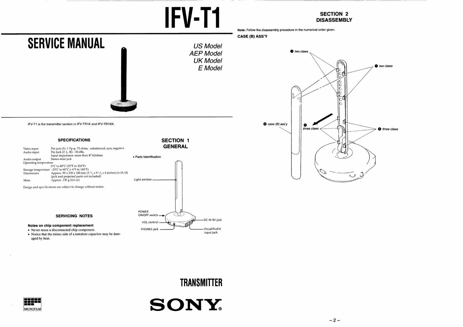
IFV-T1 is the transmitter section in IFV-TR1K and lFV-TR1KK.

SPECIFICATIONS
Video input Pin jack (1): 1 Vp-p, 75 ohms, unbalanced, sync negative
Audio input Pin Jack (2: L, R): 410 st,
Input impedance: more than 47 kilohms
Audio output Stereo mini jack

Operating temperature
0°C to 40°C (32°F to 104°F)
Storage temperature -20°C to 60°C (-4°F to 140°F)

Dimensions Approx. 95 x 230 x 100 mm (3 /4 x 9 V x 4 inches) (w/h/d)
(jack and proiected parts not included)
Mass Approx. 130 g (4.6 02)

Design and specxfications are subject to change without notice.

SERVICING NOTES

Notes on chip component replacement

0 Never reuse a disconnected chip component.

0 Notice that the minus side of a tantaIum capacitor may be dam-
aged by heaL

SECTION 1
GENERAL

. Parts Identification

Light emitter

POWER
ON/OFF switch -.§

VOL control DC IN 9V Tack

Visual/Audio
input jack

PHONES jack

TRANSMITTER
S ONY;

SECTION 2
DISASSEMBLY

Note: Follow the disassembly procedure in the numerical order given,

CASE (B) ASSY

0 case (3) my

\

o Iwoclaws

0 Moclaws

i)
\

I" t
L-4|


three claws 0 three claws

Page 2

lFV-T1

- Semiconductor
Location

Rel. No.

Location

021
022
023
024
025
026
027
028
031
D71
D99
0100
D101

|C1
|031
|C32
|C101

01
02
03
04
05
06
031
032
033
034
071
072
091
092
093
094
095
096
097
098
0101
(1102

.-
Amwwmmmmabm

o

iiaacboo

VVVAUIUIMOINN

moomoaoammi-LcoNfi

mmIIIIIImImHOOUmwOOmOO macro UJIIFHUIIIIIIII

SECTION 3

DIAGRAMS
3-1. PRINTED WIRING BOARDS

1

I

2

l3l4l516

l 7 l

8

[TX BOARD] (COMPONENT SIDE)

El

J2
PHONES

Note on Printed wiring Board:
. o- : pans extracted from the oomponeni side.
. O : Through hole.

, Patiem irom the side which enables seeing.

(The 0 er layers panems are not indicated.)

Caution:

Patten-I face side:
(Conductor Side)
Parts iaoe side:
(Componeni Side)

Parsonihe patiemiaoeside seenirom
the panem face are indicated.
Pamonmeparisiacesideseenfrom
the pans lace are indicated,