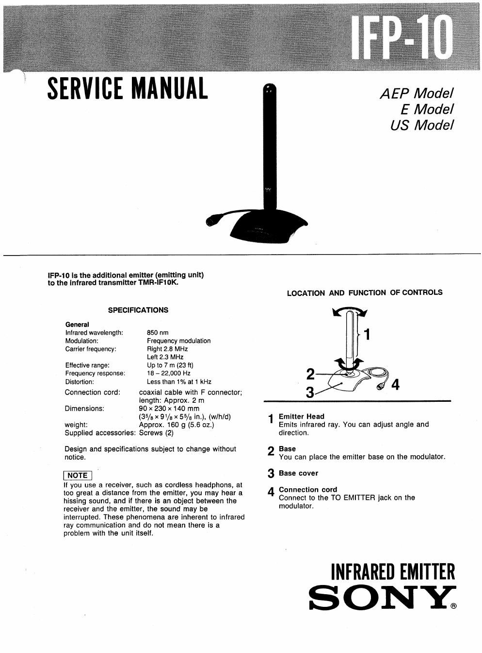
Sony ifp 10 service manual

This is the 5 pages manual for sony ifp 10 service manual.
Read or download the pdf for free. If you want to contribute, please mail your pdfs to info@audioservicemanuals.com.

Page: 1 / 5
left right
sony ifp 10 service manual

Extracted text from sony ifp 10 service manual (Ocr-read)


Page 1

SERVICE MANAL

AEP Model
E Model
US Model

lFP-to Is the addltlonal emitter (emltting unlt)
to the Infrared transmitter TMR-lF1oK.

SPECIFICATIONS
General
Infrared wavelength: 850 nm
Modulation: Frequency modulation
Carrier frequency: Right 2.8 MHz

Left 2.3 MHz

Effective range: Up to 7 m (23 ft)
Frequency response: 18 - 22,000 Hz

Less than 1% at 1 kHz

coaxial cable with F connector;
length: Approx. 2 m

90x 230 x 140 mm

(35/9 X 9/a x 5% int), (wlh/d)
weight: Approx. 160 g (5.6 oz.)
Supplied accessories: Screws (2)

Distortion:
Connection cord:

Dimensions:

Design and specifications subject to change without
notice.

It you use a receiver, such as cordless headphons, at
too great a distance from the emitter, you may hear a
hissing sound. and if there is an object between the
receiver and the emitter, the sound may be
interrupted. These phenomena are inherent to infrared
ray communication and do not mean there is a
problem with the unit itself.

LOCATION AND FUNCTION OF CONTROLS

2
3

1 Emitter Head
Emits infrared ray. You can adjust angle and
direction.

4

Base
You can place the emitter base on the modulator.

Base cover
4 Connection cord

Connect to the TO EMITTER jack on the
modulator.

INFRARED EMITTER
SONY.

Page 2

IFP-10

[CONNECTING THE MODULATOR (TMR-IF10)]

Modulator


. to T0 EMHTER 2iack
Emitter Emitter
SECTION 2
[CASE 3 AssY] DISASSEMBLY
Rfiease loggingtxlzjlaws treatments when the cover is detached.
W Splea Ing y

thumbs.

A ply a fixing compound to
portion. (Dont apply it ta

the locking claws.)
case B assy
SECTION 3
ELECTRICAL ADJUSTMENTS
[BIAS CURRENT ADJUSTMENT]

regulated dc
fig???

i \ I Q

9- RV1L

o-r-~--| : fTPtoa $5904 Tmoozngm

Procedure:

1. Feed 10.5 V dc to the pattern soldered F connector.

2. Connect a digital voltmeter to TP103 and ground.

3. Adjust with RVlOl so that the reading on the digital voltmeter
becomes to the adjusting value.
Adjusting value: 600 - 650 mV

4. Check the voltage values on TPlOl and TPlOZ become to within the
range of the adjusting value.