Sony ifmv 5 service manual

This is the 11 pages manual for sony ifmv 5 service manual.
Read or download the pdf for free. If you want to contribute, please mail your pdfs to info@audioservicemanuals.com.

Page: 1 / 11
left right
sony ifmv 5 service manual

Extracted text from sony ifmv 5 service manual (Ocr-read)


Page 1

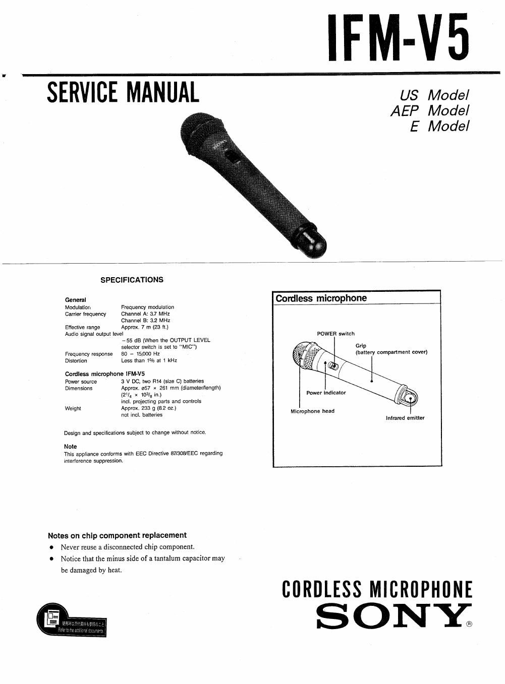
IFM-V5

SERVICE MANUAL us Model

AEP Model
E Model

SPECIFICATIONS

Geneml Cordless microphone
Modulation Frequency modulation
Gamer lrequency channel A' 37 MHz

Channel 8: 3.2 MHz
Eflective range Approx. 7 m (23 ll.)
Audio signal output level powER switch

-55 dB [When the OUTPUT LEVEL

selector switch is set lo MlC")
Frequency response 80 - 15,000 Hz

Grip
(battery compartment cover)

Distortion Less than 1% at 1 kHz

Cordless microphone IFM-VS

Power source 3 V Do, we H14 (size C) batteries
Dimensions Approx. 557 x 261 mm (diameter/length)

(2th x 103/3 in) Power indicalor
incl. projecting parts and controls

Wei hl A rox. 233 8.2 0 .
9 pp 9 I I) Microphone head

not incl. batteries
Infrared emitter

Design and specifications subject to change without notice.

Note
This appliance conforms with EEC Directive 87/308/EEC regarding
inlerlerence suppression.

Notes on chip component replacement
0 Never reuse a disconnected chip component.
0 Notice that the minus side of a tantalum capacitor may

be damaged by heat.

CORDLESS MICRllPHllNE
SONYa

Page 2

lFM-V5 1

SECTION 1
DISASSEMBLY

NOTE: Follow the disassembly procedure in the numerical order given.


0 GRIP
0 Tum the grip in the direction of
the arrow and pull out.
grip
9 Insert a thin sheet of paper
between the chassis and the. grip to
release the lock (Fig 1).
0 LED BOARD
\/ chassis
9 damper
- 9 ring, retainer
9 sheet, slide
4 mirror ass
LED board . y
a 0 screw (1.7 X 5)
0 cover
- MIC BOARD

W
/ \
LED board / \\

0 screw (1.7 X 5)

MIC board

9 screw + RKTP 2.6 X 10

_2_

0 retainer, pc board