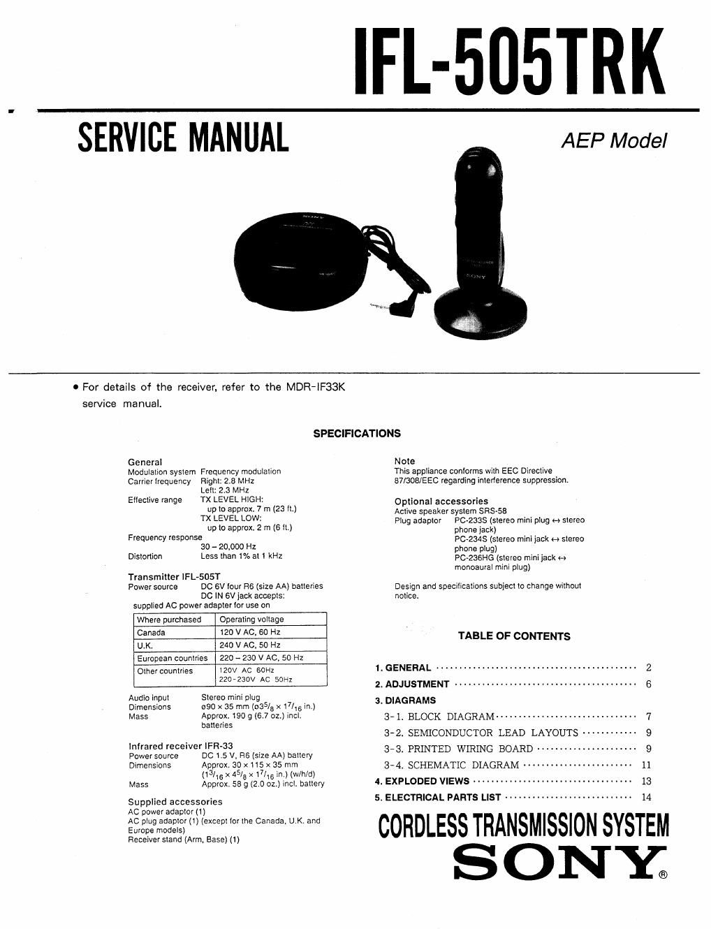
Sony ifl 505 trk service manual

This is the 13 pages manual for sony ifl 505 trk service manual.
Read or download the pdf for free. If you want to contribute, please mail your pdfs to info@audioservicemanuals.com.

Page: 1 / 13
left right
sony ifl 505 trk service manual

Extracted text from sony ifl 505 trk service manual (Ocr-read)


Page 1

IFL-5II5TRK

SERVICE MANUAL

AEP Model

0 For details of the receiver, refer to the MDR-IF33K

service manual.

SPECIFICATIONS

General
Modulation system Frequency modulation
Carrier lrequency Right: 2.8 MHz
Lell: 2.3 MHz
Effective range TX LEVEL HIGH:
up to approx. 7 m (23 ll.)
TX LEVEL LOW:
up to approx 2 m (61L)
Frequency response
30 - 20,000 HZ
Distortion Less than 1% at i kHz

Transmitter iFL-SOST
Power source DC 6V tour R6 (size AA) batteries
DO IN 6V jack accepts:
supplied AC power adapter (or use on

Where purchased Operating voltage

Canada 120 V AC. 60 Hz

LLK, 240 V AC, 50 Hz

European countries 220 ~ 230 V AC. 50 Hz

Other countries 120v AC 60H2
220-230V AC SOHZ

Audio input Stereo mini plug

Dimensions 990 x 35 mm (035/3 x 17/"; in.)

Mass Approx. 190 g (6.7 oz.) incl.
banenes

Infrared receiver iFR-33

Power source DC LS V. R6 (size AA) baltery
Dimensions Approx. 30 x115 x 35 mm

(13/15 x 45/a >< 17/3 in.) (w/h/d)
Mass Approx. 55 9 (2.0 oz.) inci. battery

Supplied accessories

AC power adaptor (1)

AC plug adaptor (1) (except ior the Canada, U.K. and
Europe models)

Receiver stand (Arm, Base) (1)

Note
This appliance contorms with EEC Directive
87/303/EEC regarding intenerence suppression.

Optional accessories

Active speaker system SFtS-Se

Plug adaptor PC-233S (stereo mini plug H stereo
phone jack)
PC-234S (stereo mini jack H stereo
phone plug)
PC-236HG (stereo mini jack H
monoaural mini plug)

Design and specifications subject to change without

notice.
TABLE OF CONTENTS

1_ GENERAL ............................................ 2
2_ ADJUSTMENT ........................................ 6
3. DIAGRAMS

3-1. BLOCK DIAGRAM ------------------------------- 7

3'2. SEMICONDUCTOR LEAD LAYOUTS ~~~~~~~~~~~~ 9

3-3. PRINTED WIRING BOARD ------- - - - , e . --------- 9

3-4. SCHEMATIC DIAGRAM ------------------------ 11
4. EXPLODED VIEWS .................................. 13
5. ELECTRICAL PARTS LIST ~~~~~~~~~~~~~~~~~~~~~~~~~~~~

CORDLESS TRANSMISSION SYSTEM

SONY.