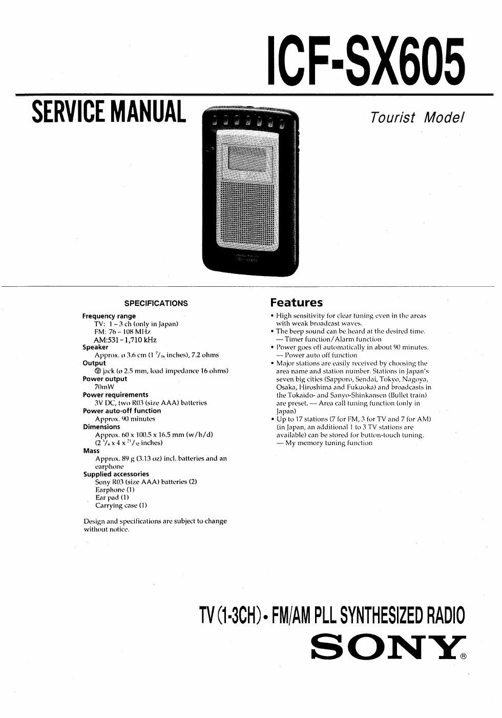
Sony icf sx 605 service manual

This is the 16 pages manual for sony icf sx 605 service manual.
Read or download the pdf for free. If you want to contribute, please mail your pdfs to info@audioservicemanuals.com.

Page: 1 / 16
left right
sony icf sx 605 service manual

Extracted text from sony icf sx 605 service manual (Ocr-read)


Page 1

SERVICE MANUAL

ICF-SX605

Taur/sz Model

SPECIFICATIONS

Frequency range
TV: 1 - 3 ch (only in Japan)
FM: 76- IOB MHZ
AM1531- 1,710 kHz
Speaker
Approx. 0 3,6 cm (i 7m inches), 7.2 ohms
Output
(3 jack to 2,5 mm, load impedance 16 ohms)
Power output
70an
Power requirements
3V DC, two RIB (size AAA) batteries
Power auto-off function
Approx 90 minutes
Dimensions
Approx. 64) x 100.5 x165 mm (w/h/d)
(2 /x x 4 x "/u inches)
Mass
Approx. 89 g (3.13 07.) incli batteries and an
earphone
Supplied accessories
Sony R03 (size AAA) batteries (2)
Earphone (I )
Ear pad (I)
Carrying case (I)

Design and specifications are subject to change
without notitc.

Features

' High sensitivity {or clear tuning even in the areas
with weak broadcast waves.

' The beep sound can be heard at the desired time.
- Timer function/Alarm iunction

0 Power goes off automatically in about 90 minutes.
- Power auto oft function

' Major stations are easily received by choosing the

area name and station number. Stations in Japans

seven big cities (Sapporo, Sendai, Tokyo, Nagoya,

Osaka, Hiroshima and Fukuoka) and broadc is in

the Tokaidu» and Sanyo-Shinkansen (Bullet train)

are preset. - Area call tuning lunction (only in

Japan)

Up to l7 stations (7 for FM, 3 for TV and 7 for AM)

(in Japan, an additional 1 lo 3 TV stations are

available) ran be stored (or button~touch tuning.

- My memory tuning function

TV (l-3CH)° FM/AM PLL SYNTHESIZED RADIO

SONY.

Page 2

TABLE OF CONTENTS

Specifications"- ..1
1. GENERAL ................................................................ 3
2. DISASSEMBLY

2~1. Lid, Battery Case Removal-~ ----- 7

2-Zl Cabinet (Rear) Removal ~-

2-3. Main Board Removal -.7
3. ELECTRICAL ADJUSTMENTS --------------------------------- 8
4. EXPLANATION OF lc TERMINALS ............................ 9
5. DIAGRAMS

5.1 Printed Wiring Boards .......................................... 11

5.2 Schematic Diagram .............................................. 13
6. EXPLODED VIEW -------------------------------
7. ELECTRICAL PARTS LIST ~~~~~~~~~~~~~~~~~~~~~~~~~~~~~~~~~~~~~ l7

0 HOW TO CHANGED THE CERAMIC FILTERS

This model is used two ceramic filteis of CH and CFZ.

You must used same type of color marked ceramic filters in
order to meet same specifications '

Therefore, the ceramic filter must changed two pieces together
since its supply two pieces in one package as a spare parts.

Wk 'ak Mark frgggéenlcy
red 10.70MHZ

blue 10,67MHZ

orange 10,73Ml-lz

black 10.64MHZ

white 10.76MH1

Notes on chip component replacement

0 Never reuse a disconnected chip component.
0 Notice that the minus side of a tantalum capacitor
may be damaged by heat.