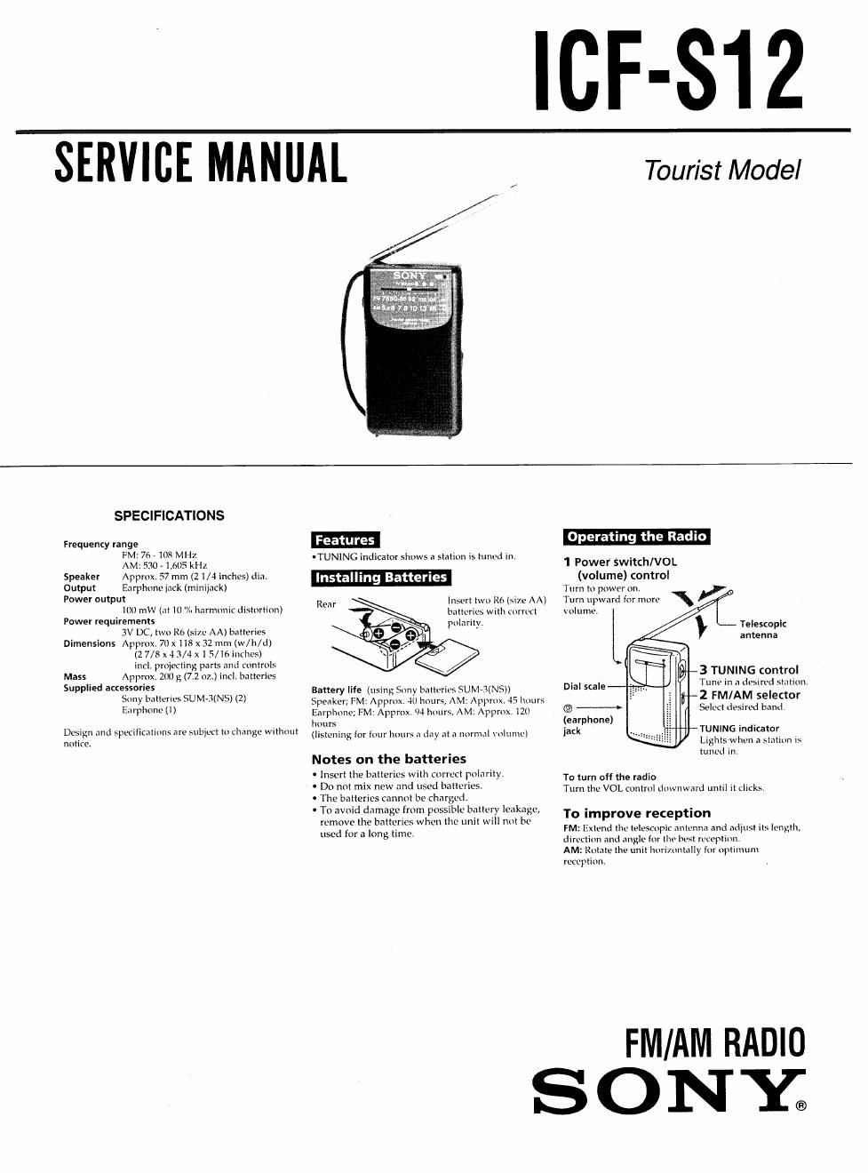
Sony icf s 12 service manual

This is the 7 pages manual for sony icf s 12 service manual.
Read or download the pdf for free. If you want to contribute, please mail your pdfs to info@audioservicemanuals.com.

Page: 1 / 7
left right
sony icf s 12 service manual

Extracted text from sony icf s 12 service manual (Ocr-read)


Page 1

ICF-S12

SERVICE MANUAL

t
1
3*

5
c
r.
i
t

Tourist Model

SPECIFICATIONS

Frequeney range
FM 76 - 108 MH7
AM: 530 - 1,605 kHz

Speaker Approx 57 mm (2 1/4 inches) dinv
Output Enrphnnc iack (minijack)
Power output

ltllI mV\ (at 10% harmonic distortion)
Power requirements
3V DC, two R6 (him AA) batteries
Dimensions Approx 7t) x m x 32 mm (w/h/d)
(27/8 x 4 3/4 x 1 5/16 inthcs)
incl. pmiecling parts and mntrnls
Mass Approx 2m: 3; (7.2 07..) incl. batteries
Supplied accessories
Sony batteries SUM»J(N5) (2)
Earphone (l)

Dcsrgn and specifications are subject tn change without
nntire.

0TUNING indicator shows a station is tum'd In

stal 'ng Batteries

Insert two R6 (Si7e AA)
batteries with cnrrucl
polarity.

Rear

Battery life (using Sony batteries SUM-3(NS)|
Speaker; FM: Apprnx, in httum, AM, npprnx. 45 hours
Earphone; FM: Approx, 94 hnurs, AM: Apprnx I20
hours

(listening for four hours .1 day at n nnrnul volume)

Notes on the batteries

. Insert the batteries with correct polarity

0 Do not mix new and used batteries.

0 The batteries cannot be charged,

. To avoid damage from possible battery leakage,
remove the batteries when the unit will not be
used [or a long time.

Operat ng the Rad o

1 Power SwitchNOL
(volume) control
Turn to pnwer on
Turn upward for mnre
vol ume.

Telescoplc
antenna

3 TUNING control

Tune in a desired station,

Dial scale
2 FM/AM selector

® Select desired band
(earphone)
jack " TUNING indicator

Lights whcn a .stntirm i»-
tuned in.

To turn off the radio
Turn the VOL cuntml downward until it clicks

To improve reception

FM: Extend the telescnpir antenna and adjust its length,
dirvcliun and angle for tho host rtwptlnn.

AM: Rotate the unit Imrimnmlly tor npttmum
retcptiunt

FM/AM RADIO

SON'E

Page 2

SECTION 1

DISASSEMBLY

Note: Follow the disassembly procedure in the numerical order given.

REAR CABINET REMOVAL MAIN BOARD MOUNTING

0 Remove the battery case lid

3 9 +BTP2,6 x a

rear cabinet

POINTER SETTING

pointer

pointer

l:>


stopper

arrow direction to the
stopper.

0 Slide the pointer
to the VT marked position.

0 Turn variable capacitor
fully counterclockwise.

6 Return the pointer in the

cabinet (rear)

main board

cabinet
(front)

cabinet (rear)

ANT1

KNOB (TUNING) INSERTION

0 Turn the holed position of
the knob (tuning) to the arrow
direction and insert the knob
(tuning) so as to engage with
the pointer surely.

0 hole

W
\ knob (tuning)