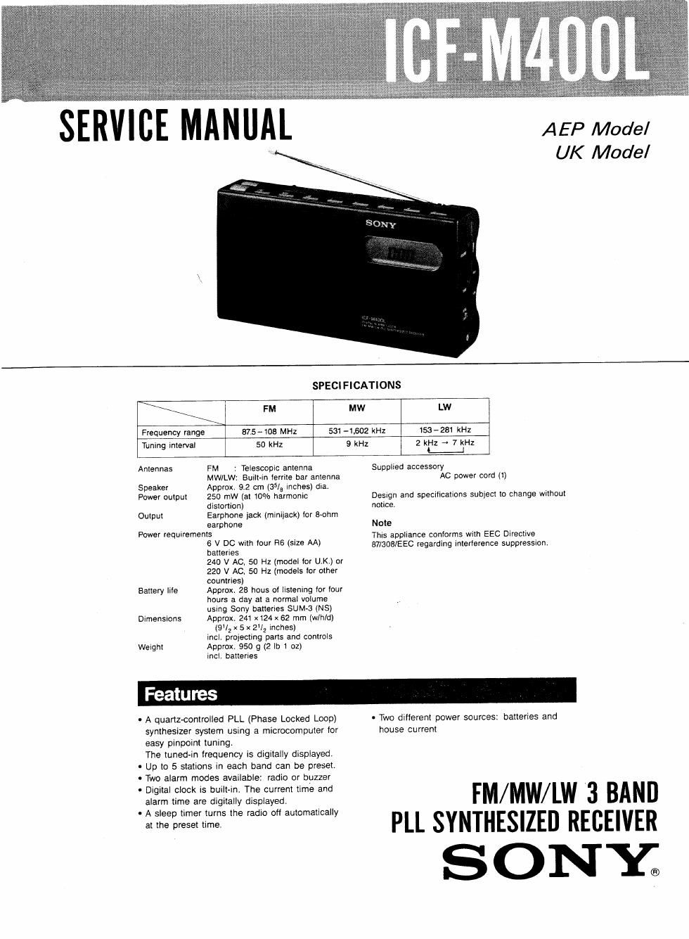
Sony icf m 400 l service manual

This is the 13 pages manual for sony icf m 400 l service manual.
Read or download the pdf for free. If you want to contribute, please mail your pdfs to info@audioservicemanuals.com.

Page: 1 / 13
left right
sony icf m 400 l service manual

Extracted text from sony icf m 400 l service manual (Ocr-read)


Page 1

AEP Model
UK Model

SERVICE MANUAL

SPECIFICATIONS

FM MW LW
Frequency range 875-108 MHz 531 4,602 kHz 153-231 kHz
Tuning interval 50 kHz 9 kHz 2 kHz -~ 7 kHz
L_J

Antennas FM : Telescopic antenna
MW/LW: Built-in lerrite bar antenna

Speaker Approx. 9.2 cm (35/9 Inches) dia.

Power output 250 mW (at 10% harmonic
distortion)

Output Earphone jack (miniiack) lor S-ohm
earphone

Power requirements
6 V DC with lour R6 (size AA)
benenes
240 V AC, 50 Hz (model (or UK.) or
220 V AC. 50 Hz (models for other
countries)
Approx 28 hous of listening ior four
hours a day at a normal volume
using Sony batteries SUM-3 (NS)
Approx. 241 x124 x 62 mm (w/hld)

(9!2 x 5 x 2I2 inches)
incl. propecting parts and controls
Weight Approx. 950 g (2 lo 1 oz)

incl. batteries

Battery lite

Dimensions

Supplied accessory
AC power cord (1)

Design and specifications subject to change without
notice.

Note
This appliance conforms with EEC Directive
87/308/EEC regarding interierence suppression.

0 A quartz-controlled PLL (Phase Locked Loop)
synthesizer system using a microcomputer for
easy pinpoint tuning,

The tuned-in frequency is digitally displayed.
' Up to 5 stations in each band can be preset.
0 Two alarm modes available: radio or buzzer
- Digital clock is built-in. The current time and

alarm time are digitally displayed

0 A sleep timer turns the radio off automatically
at the preset time.

- Two ditlerent power sources: batteries and
house current

FM/MW/LW '3 BAND
PLL SYNTHESIZED RECEIVER

ONY.

Page 2

IC M400L

SAFETY-RELATED COMPONENT WARNING! !

COMPONENTS IDENTIFIED BV MARK A OR DOTTED
LINE WITH MARK A ON THE SCHEMATIC DIAGRAMS
AND IN THE PARTS LIST ARE CRITICAL TO SAFE
OPERATION. REPLACE THESE COMPONENTS WITH
SONY PARTS WHOSE PART NUMBERS APPEAR AS
SHOWN IN THIS MANUAL OR IN SUPPLEMENTS PUB-

LISHED BY SONY.

[:1 Location of Controls

@ How to Set the Clock

SECTION 1
GENERAL

LocaIion of Controls

m SCAN/TIME AN (adj-memo!) +1-
buttons

2 Tempic InInnn:

: SLEEP button

4 OFF Indium
AI: IN jack (Ian eIde)

E] POWER omamm FMIMWILw
huuonl

7 Speaker

a Emery companmem (bonom)

fl ENTER bunpu

m TIME SET CLOCK button

"I ALARM bunon

1 ALARM mode seIemor (RADIO/BUZZER)

x: ALARM sET nunen

w VOLUME comm!

I TONE com-cl
I SENS Dx/UJCAL nectar

I 1 ® (earphone) lack
E DIspI-y window
\Ls; Pnassr TUNING humans

B How to Set the Clock

1 Keep In. TIME SET CLOCK bunnn pressed. who", gym, model "0, UN
Ind m-n pull me TIME AN e or - 1 AM 12:00 2. WNW
m" MWY' PM 12:00 e Noon
When me + 01 - mmon is Item pressed, The

digis are rapidly Wanted um" system model (In: omev pounmes)

a oo = Miamgm
2 Halal-u The TIME SET cwcx punpn. 12m = NW
The clock WI" begun Io ODEGIB.
To set my time many lo (ha mend mm .
- The anneal |Ime can he sex even when me Mew, m ng
'5 5 °"- Example: In m to 7:15 lo the second
. Tue cunem mne IS a-spIayea when we ram: ,
35 on. 1 Se Ihs lune w 7-15 and keep the TIME SET

CLOCK punon messed.
2 ReIease The TIME SET CLOCK buuon
sumunaneeust w-m me Ielephone ume sxgnaI.