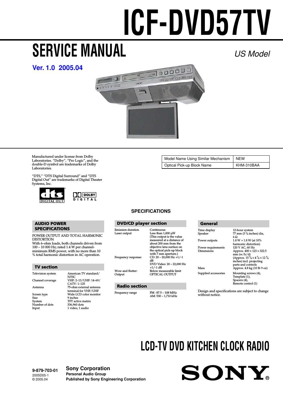
Sony icf dvd 57 tv service manual

This is the 94 pages manual for sony icf dvd 57 tv service manual.
Read or download the pdf for free. If you want to contribute, please mail your pdfs to info@audioservicemanuals.com.

Page: 1 / 94
left right
sony icf dvd 57 tv service manual

Extracted text from sony icf dvd 57 tv service manual (Ocr-read)


Page 1

ICF-DVD57TV

SERVICE MANUAL

Ver. 1.0 2005.04

US Model

Manufactured under license fmrn Dolby
Laboratories. Dolby", "Pro Logic, and the
double-D symbol are trademarks of Dolby
Laboratories.

DTS, DTS Digital Surround and DTS
Digital Out" are trademarks of Digital Theater
Systems, Inc.

DIGITAL OUT

AUDIO POWER
SPECIFICATIONS

POWER OUTPUT AND TOTAL HARMON'IC
DISTORTION

With 6-ohm loads, both channels driven from
100 - 10 000 Hz; rated 1.4 W per channel-
minimum RMS power, with no more than 10
A. total harmonic distortion in AC operation.

TV section

Television system American TV standazd/
ms:

Channel coverage VHF: ZrlS/UHF: 14-69/
CATV: 17125

Antenna 75 terminal for VHF/UHF

screen type Wide LCD color monitor

Size 9 inches

System TFT active matrix

Number of dots 335,950 dots

Input 1 video, 1 audio

9_879_703_01 Sony Corporation

20050054 Personal Audio Group

© 2005.04

Published by Sony Engineering Corporation

Model Name Using Similar Mechanism NEW

Optical Pick-up Block Name

KHM-31OBAA

SPECIFICATIONS

DVD/CD player section

Emission duration
Laser output

Continuous
Less than 1,000 pw

(ihrs output is the value
measured at a distance of
about 200 mm from the
objective lens surtace on
the optical pickup black
With 7 mm aperture.)

Frequency response: CD: 20 e 20,000 Hz +1 /71

dB
DVD Video: 20 r 22,000 Hz
+1 /*1 dB
Wow and flutter: Below measurable limit
Output OPTICAL OUTPUT

Radio section

FM: 87.5 r 108 MHz
AM: 530 r 1,710 kHz

Frequency range

General
Time display erhour system
Speaker 77 mm (3 4, inches) dia,

6 D.
1.8 W + 1.8 W (at 10%
harmonic distortion)

Power outputs

Power requirements 120 v AC, 60 Hz
Dimensions Approx. 400 x 123 x 322.5
mm (w/h/d)

(Approx. 15 3/4 x 4 /t x 12 3/4
inches) incl. projecting
parts and controls

Mass Approx. 4.3 kg (10 lb 9 oz)

Supplied accessories Mounting screws (4),
Template (1),
spacers (4),

Remote control (1)

Design and specifications are subject to change
without notice.

LCD-TV DVD KITCHEN CLOCK RADIO

SONY.

Page 2

ICF-DVD57TV

Notes on chip component replacement
I Never reuse a disconnected chip Component.
0 Notice that the minus side of a tantalum capacitor may be
damaged by heat.

Flexible Circuit Board Repairing
I Keep the temperature of the soldering iron around 270 C
during repairing.
I Do not touch the soldering iron on the same conductor of the
circuit board (within 3 times).
I Be careful not to apply force on the conductor when soldering
or unsoldering.

SAFETY CHECK-OUT

After correcting the original service problem, perform the following
safety check before releasing the set to the customer:

Check the antenna terminals, metal trim, metallized knobs, screws,
and all other exposed metal parts for AC leakage.

Check leakage as described below.

LEAKAGE TEST

The AC leakage from any exposed metal part to earth ground and
from all exposed metal parts to any exposed metal part having a
return to ch s, must not exceed 0.5 mA (500 microamperes).
Leakage current can be measured by any one of three methods.

1. A commercial leakage tester, such as the Simpson 229 or RCA
WT-540A. Follow the manufacturers instructions to use these
instruments.

2. A battery-operated AC milliammeter. The Data Precision 245
digital multimeter is suitable for this job.

3. Measuring the voltage drop across a resistor by means of a
VOM or battery-operated AC voltmeter. The limit" indication
is 0.75 V, so analog meters must have an accurate low-voltage
scale. The Simpson 250 and Sanwa SH-63Trd are examples
ofa passive VOM that is suitable. Nearly all battery operated
digital multimeters that have a 2 V AC range are suitable. (See

Fig. A)
To Exposed Metal
Parts on Set
AC
0. 15 uF g 1.5 k9 / voltmeter
(0.75 V)

_7_ Earth Ground
Fig. A. Using an AC voltmeter to check AC leakage.

SAFETY-RELATED COMPONENT WARNING !!

COMPONENTS IDENTIFIED BY MARK A OR DOTTED LINE
WITH MARK A ON THE SCHEMATIC DIAGRAMS AND IN
THE PARTS LIST ARE CRITICAL T0 SAFE OPERATION.
REPLACE THESE COMPONENTS WITH SONY PARTS WHOSE
PART NUMBERS APPEAR AS SHOWN IN THIS MANUAL OR
IN SUPPLEMENTS PUBLISHED BY SONY.

2

CAUTION

Use of controls or adjustments or performance of procedures
other than those specified herein may result in hazardous radiation
exposure.

About the discs this unit
can play

This unit can play the following discs:
I DVD VIDEO

I DVDeR/ DVD+R

I DVDeRW/DVD+RW

I Video CD
I Audio CD
I CDeR/CDeRW
Disc type Label on the disc
DVD Videos %
v I D E o"
R w i I
nvnmewmue nvnsa
Video CD @figfi
Audio CDs cnmnacr DDMDACY
DIGIYAL AUDID DIGITAL AUDIO
EDMPMT
DIGITALAUDID
ReWritable

DVD VIDEO," DVDeR" and DVDeRW are
trademarks.

Discs that this system cannot play

' CDeROMs

I CDeRs/CD-RWs other than those recorded in
the following formats:
~ music CD format
-- video CD format

I Data part of CDAExtras

I Super Audio CDs

I DVDeROMs

I DVD-RAMS

I DVD Audio discs

I 8 cm(3 inches) DVD discs

I Photo Movies created after recording in VR
mode by DVD Handycam.

I Progressive JPEG format file

I Discs with nonestandard shapes (e.g., heart,
square, star) cannot be played on this unit
Attempting to do so may damage the unit.
Do not use such discs.

I A disc with paper or stickers on it

I A disc that has the adhesive, cellophane tapel
or a sticker still left on it.

t A logical format of files and folders on a CD
ROMS, defined by ISO (International
Organization for standardiza tion).