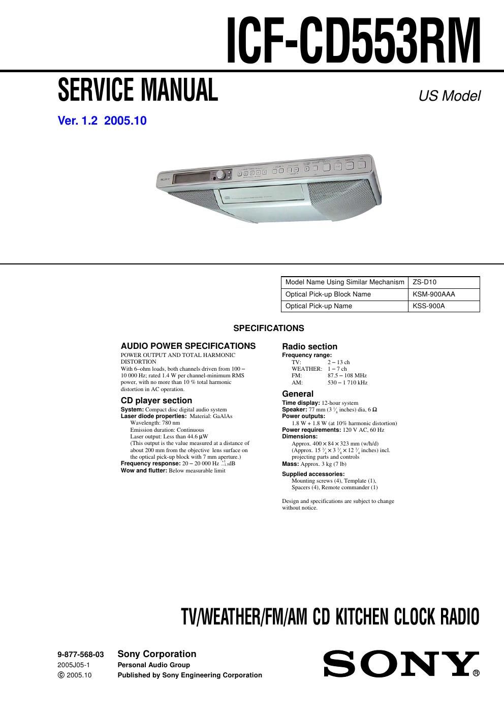
Sony icf cd 553 rm service manual

This is the 50 pages manual for sony icf cd 553 rm service manual.
Read or download the pdf for free. If you want to contribute, please mail your pdfs to info@audioservicemanuals.com.

Page: 1 / 50
left right
sony icf cd 553 rm service manual

Extracted text from sony icf cd 553 rm service manual (Ocr-read)


Page 1

ICF-CD553RNI

SERVICE MANUAL

Ver. 1.2 2005.10

US Model

Model Name Using Similar Mechanism ZS-D10

Optical Pick-up Block Name KSM-BOOAAA

KSS-QOOA

Optical Pick-up Name

SPECIFICATIONS

AUDIO POWER SPECIFICATIONS
POWER OUTPUT AND TOTAL HARMONIC
DISTORTION

With firollnl loads. both channels driven from 100 -

[0 000 Hz; rated 1.4 w per challnelrlnintnlum RMS
power. with no more than 10 7? total harmonic
distortion in AC aperaircn.

CD player section
System: Compact disc digital audio system
Laser diode properties: Material: GaAlAs
Wavelength: 780 nm
Emission duration: Continuous
Laser output: Less than 44.6 uw
(This output Is the value measured at a (IISIAHCE of
about 200 mm from the objective lens surface on
the optical pickrup block W|lIl 7 mm aperture.)
Frequency response: 20 - 20 000 H
Wow and flutter: Below measurable limit

Radio section
Frequency range:

TV: 2 - 13 ch

WEATHER: l -7cll

FM: 87.5 ~ 108 MHz

AM: 530- l 710 kHz
General

Time display: llrhour system
Speaker: 77 mm (3 /x inches) dia, 6 £2
Power outputs:

1.8 W + 1.8 W (at 10% harmonic distortion)
Power requirements: 120 V AC. 60 Hz
Dimensions:

Approx. 400 x 84 x 323 mm (w/h/d)

(Approx. 15 4 X 3 /X X 12 4 Inches) incl.

projecting parts and controls
Mass: Approx. 3 kg (7 lb)

Supplied accessories:
Mouniing screws (4). Template (1).
Spacers (4). Remote commander (I)

Design and Specifications are Subject to change
without natice,

TII/WEATHER/FM/AM CD KITCHEN CLOCK RADIO

9-877-568-03 Sony Corporation
2005J05-1 Personal Audio Group
© 2005.10 Published by Sony Engineering Corporation

SONY®

Page 2

ICF-CD553RM

Notes on chip component replacement

0 Never reuse a disconnected chip component.

0 Notice that the minus side of a tantalum capacitor may be dam-
aged by heat.

Flexible Circuit Board Repairing

0 Keep the temperature of the soldering iron around 270 °C dur-
ing repairing.

- Do not touch the soldering iron on the same conductor of the
circuit board (within 3 times).

0 Be careful not to apply force on the conductor when soldering
or unsoldering.

SAFETY CHECK-OUT

After correcting the original service problem, perform the follow-
ing safety Check before releasing the set to the customer:

Check the antenna terminals, metal trim, metallized knobs,
screws, and all other exposed metal parts for AC leakage.

Check leakage as described below.

LEAKAGE TEST

The AC leakage from any exposed metal part to earth ground and

from all exposed metal parts to any exposed metal part having a

return to chass , must not exceed 0.5 mA (500 microamperes).

Leakage current can be measured by any one of three methods.

1. A commercial leakage tester, such as the Simpson 229 or RCA
WTA540A. Follow the manufacturers instructions to use these
instruments.

2. A battery-operated AC milliammeter. The Data Precision 245
digital multimeter is suitable for thisjob.

3. Measuring the voltage drop across a resistor by means of a
VOM or batterycoperated AC voltmeter. The limit indicae
tion is 0.75 V, so analog meters must have an accurate low
voltage scale. The Simpson 250 and Sanwa SH-63Trd are ex-
amples of a passive VOM that is suitable. Nearly all battery
operated digital multimeters that have a 2 V AC range are suit
able. (See Fig. A)

CAUTION
Use of controls or adjustments or performance of procedures
other than those specified herein may result in hazardous ra-

diation exposure.

To Exposed Mela!
Parls on Set

A C
/ voltmeter
(0. 75 V)

0.15pF

g 1.5 M]

_7_ Earth Ground
Fig. A. Using an AC voltmeter to check AC leakage.

SAFETY-RELATED COMPONENT WARNING !!

COMPONENTS IDENTIFIED BY MARK A OR DOTTED
LINE WITH MARK A ON THE SCHEMATIC DIAGRAMS
AND IN THE PARTS LIST ARE CRITICAL TO SAFE
OPERATION. REPLACE THESE COMPONENTS WITH
SONY PARTS WHOSE PART NUMBERS APPEAR AS
SHOWN IN THIS MANUAL OR IN SUPPLEMENTS PUB-
LISHED BY SONY.

About CD-Rs/CD-RWs

This unit is compatible with CDRS/CDVRWS but
playback capability may vary depending on the
quality of the disc the recording device and
application software.