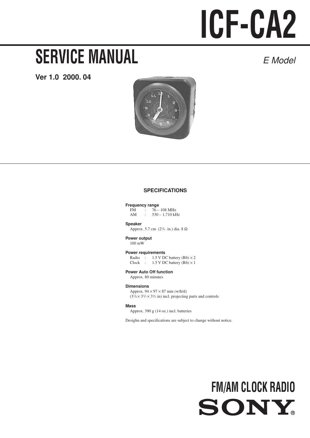
Sony icf ca 2 service manual

This is the 12 pages manual for sony icf ca 2 service manual.
Read or download the pdf for free. If you want to contribute, please mail your pdfs to info@audioservicemanuals.com.

Page: 1 / 12
left right
sony icf ca 2 service manual

Extracted text from sony icf ca 2 service manual (Ocr-read)


Page 1

Ñ 2 Ñ TABLE OF CONTENTS 1. GENERAL ááááááááááááááááááááááááááááááááááááááááááááááááááá\ ááááááááááááááááááááááá 2 2. DISASSEMBLY 2-1. CABINET (REAR) AND CLOCK áááááááááááááááááááááááááááááááááááá 3 2-2. KNOB (TUN) (BAND) (VR) ááááááááááááááááááááááááááááááááááááááááááááá 4 2-3. MAIN BOARD ááááááááááááááááááááááááááááááááááááááááááááááááááá\ ááááááááááááááá 4 3. ADJUSTMENT ááááááááááááááááááááááááááááááááááááááááááááááááááá\ áááááááááááááá 6 4. DIAGRAM 4-1. IC Block Diagram ááááááááááááááááááááááááááááááááááááááááááááááááááá\ ááááááááááá 7 4-2. Printed Wiring Board ááááááááááááááááááááááááááááááááááááááááááááááááááá\ ááááááá 8 4-3. Schematic Diagram ááááááááááááááááááááááááááááááááááááááááááááááááááá\ ááááááááá 9 5. EXPLODED VIEWS ááááááááááááááááááááááááááááááááááááááááááááááááááá\ ááá 11 6. ELECTRICAL PARTS LIST ááááááááááááááááááááááááááááááááááááááá 12 SECTION 1 GENERAL Notes on chip component replacement ¥ Never reuse a disconnected chip component. ¥ Notice that the minus side of a tantalum capacitor may be damaged by heat. Flexible Circuit Board Repairing ¥ Keep the temperature of soldering iron around 270ûC during repairing. ¥ Do not touch the soldering iron on the same conductor of the circuit board (within 3 times). ¥ Be careful not to apply force on the conductor when soldering or unsoldering. This section is extracted from instruction manual.

Page 2

Ñ 3 Ñ SECTION 2 DISASSEMBLY Note :Follow the disassembly procedure in the numerical order given. · The equipment can be removed using the following procedure. 2-1. CABINET (REAR) AND CLOCK knob (tun) (band) (vr) Cabinet (rear) and clock Set Main boar d ¥ NOTE ON INSTALLING CONNECTION CORD 2 Knob (TIME SET) 3 Two screws (P3 x 16) 4 Cabinet (rear) 1 Lid, battery case 7 Clock (It has a claw) 6 CN1 (6P) Claws 5 Connection cord Cloc k To Main board CN1.