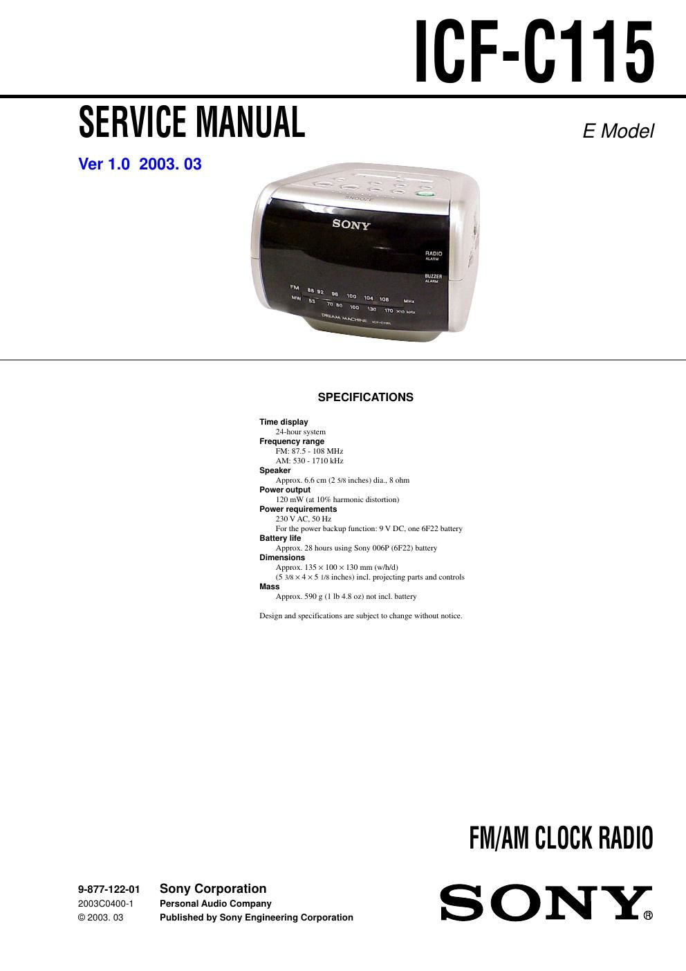
Sony icf c 115 service manual

This is the 20 pages manual for sony icf c 115 service manual.
Read or download the pdf for free. If you want to contribute, please mail your pdfs to info@audioservicemanuals.com.

Page: 1 / 20
left right
sony icf c 115 service manual

Extracted text from sony icf c 115 service manual (Ocr-read)


Page 1

2 SAFETY-RELATED COMPONENT WARNING!! COMPONENTS IDENTIFIED BY MARK 0 OR DOTTED LINE WITH MARK 0 ON THE SCHEMATIC DIAGRAMS AND IN THE PARTS LIST ARE CRITICAL TO SAFE OPERATION. REPLACE THESE COMPONENTS WITH SONY PARTS WHOSE PART NUMBERS APPEAR AS SHOWN IN THIS MANUAL OR IN SUPPLEMENTS PUBLISHED BY SONY. Notes on Chip Component Replacement -Never reuse a disconnected chip component. -Notice that the minus side of a tantalum capacitor may be dam- aged by heat. ICF-C115 TABLE OF CONTENTS 1. SERVICING NOTES 1-1. Cord Dressing (Power Cord) ............................................... 3 1-2. Pointer Alignment ............................................................... 3 2. GENERAL Installing the Battery ............................................................... 4 Setting the Clock ..................................................................... 4 Operating the Radio ................................................................. 4 Setting the Alarm ..................................................................... 4 Setting the Sleep Timer ........................................................... 4 3. DISASSEMBLY 3-1. Panel (Front) ........................................................................ 5 3-2. Cabinet (Upper) Dual Assy ................................................. 6 3-3. Main Board Section ............................................................ 6 3-4. Main Board, LED101 .......................................................... 7 4. ELECTRICAL ADJUSTMENTS ................................... 8 5. DIAGRAMS 5-1. Block Diagram .................................................................. 11 5-2. Printed Wiring Boards ....................................................... 12 5-3. Schematic Diagram ........................................................... 13 5-4. IC Block Diagrams ............................................................ 14 6. EXPLODED VIEWS 6-1. Cabinet (Upper) Section .................................................... 15 6-2. Main Board Section .......................................................... 16 7. ELECTRICAL PARTS LIST ......................................... 17

Page 2

3 ICF-C115 SECTION 1 SERVICING NOTES 1-2. POINTER ALIGNMENT 1-1. CORD DRESSING (POWER CORD) 1) Set the power cord as shown in the figure. 2) Mount the chassis with power cord retainerboard and screws (P 3 × 10). Note: Tighten completely the screws (P 3 × 10). screw P 3x10 power cord retainer boar d power cord 6 P 3x10 4 3 1 pointer 2 knob (tuning) 5 MAIN board chassis