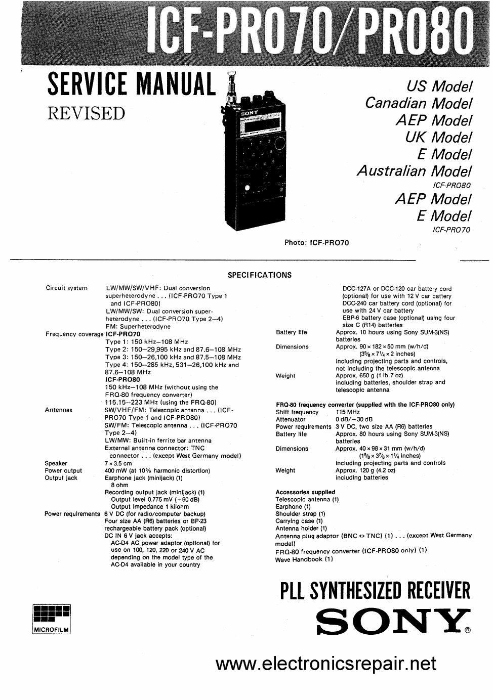
Sony icf pro70

This is the 56 pages manual for sony icf pro70.
Read or download the pdf for free. If you want to contribute, please mail your pdfs to info@audioservicemanuals.com.

Page: 1 / 56
left right
sony icf pro70

Extracted text from sony icf pro70 (Ocr-read)


Page 2

lCF-PRO70/PR080

LFEATURES |
{WORLD-WIDE FREQUENCY COVERAGE l

TABLE OF CONTENTS

No band selector is provided. £01121 fle- IE1
The entire frequency range is tuned in . . _
consecutively. The detection mode is set specmcatmns ---------------------- I
automatically according to the frequency range to Features -------------------------- 2
which the tuned frequency belongs.
1. GENERAL
Selectable detection modes . . Notes on Model Types and Receivable
(Except lCF-PHO7O West Germany and Saudi Arabia F . 3
odel) requenctes ........................
m . . . . , To Change the MW Tuning Interval ........ 3
The entire frequency coverage is lelded into 2 to T E e All Memo: 3
4 ranges depending on the model type, and the 0 f _y f'C t 1 """""
detection modes, FM, NARROW FM, AM WIDE, WW a? Fund! ° 0 ° 5 rrrrrrrr 4
AM NARROW and 333* can be selected for each Direct Tumg ---------------------- 6
range. Memory Tuning ..................... 7
$53 = Slhgla sld. Band Manual Tuning ...................... 8
Scan Tuning . . .................. 9
Frequency converter supplied for wider coverage Limited Scan Tuning .................. 10
(lCF-PROBO only) Memory Scan Tuning ................. 10
By attaching the supplied FR080 frequency Program Memory Scan Tuning ........... ll
converter, 115.15s223 MHz can also be received. gammy Tuning _____________________ 12
To Select the Detection Mode ..... . , 12
l VERSATILE TUNING MODES I Fine Tuning ........................ 13
To Convert the Frequency Coverage
D'gfng'flggfiaflncy m be mm in nwnen you know the trequency oi lhe Station (ICF~P R080 only) ................. 14
Mommy inning [Page 7)
by I p ' b it tot no n the at red 'Fordaly listening to In one st t'on
3.3.5.23. "W °"° °" ' ° ' W V ' 2. ELECTRICAL ADJUSTMENTS
M H I {P 8) Wh fl lk thl llh. tt'
:3";an"£n§n232ncis m by sup .. a «tunnel -Ta 53.3. 912%.; thsfon'iifiilié I; sit: .Tg Reference-Frequency OSCfllator (7.2 MHz)
interval or limited scan tuning precisely Adjustment ....................... 16
5!: m i (P 9) , '
t3 Willem scanning the entire treatiency . When you do not know the llequertcy oi the station VCOI PD Voltage .Adjustment """""" 17
coverage FM~L Tracking Adjustment ............. l7
Um'lld t l (P 10) 'Whon 0 k th I c n n h th '
s; .it2::..§§l.;iui§.;g me lrequency m... you may ism. .1;-§:?2J?L§'i"iww Sign VCOZ PD 35 édlusme ---------- 18
have defined broadcasting lance. an 5W meter band). FM-H Tracking Adjustment . . . . . . 18
Mm 1" m (Page '0) ' To choose a station irom among those stored in a FM IF AdjJStment ---------------- 19
b t ' ll lh l red i 0) .
Jsfifinlmm y mm a so (up 0 mm mm 9"" Second Local Oscillator Adjustment ........ 19
New" WW m" 13 (Page "l , _ AM lst and 2nd IF Adjustment ........... 20
by automdtlcally scanning only the stations you have - To choose a station trom among those home the ,
programmed among all stored in memory (up lo 40 specified condition: (19. FM hroadcastlng stations) NARROW-FM Detector Adjustment
stations) in the order programmed AM AGC Adjustment
Priortty tuning lFaga 12) - re catch a radio communication when you are not """""
by tuning in the lmified station every 3 seconds sure when It will like plaice.

l CONVENIENT FUNCTIONS

Memory or up to to Imlonl (Pace 7)

Up to 40 stations can be stored on A memory page: (10 stations (or
each page) and tuned in instantly.

Thin Icon mode: eel-cluel- (Page 9)

Scanning can be stopped at the first-located station. or be resumed
arty each station located has been "(:de tor several seconds or
will the signll 0' In. station 51005,

Memory union (Page 7)

Th. lreouenciu or the station: stored on one page are dlsolayed in
sequence while your dwred station I: klpl tuned in.

Program mama-lei. Page")

the Irequoncles at the stations programmed are displayed in sequence
while your desired station il up! tuned in.

Memory protection (Page 7)

The memory or one page (10 stations stored) is locked so that it
cannot be changed inadvertently.

Kay WM (Pads 5)

The button: on the front panel are locked so that they cannot be
operated by accident.

Sqmlch control (Page 9)

Thu receivable signal level can be adjusted so tnst scanning stops at
stations with stronger signals only and noise is suppressed while
timing and while no station signal is present.

Flnl inning (Page is)

AM lLW. MW and SW) and 355 stations can be tuned in precisely.

-2...

3. DIAGRAMS

lC Block Diagrams ................... 21
Semiconductor Lead Layouts ............ 22
3-1. Signal, PLL Section

Printed Wiring Boards ............. 23
3-2. Schematic Diagram ............... 27
3-3. Converter Board Schematic Diagram . . i 30
3-4. Control Section Printed Wiring Boards . . 30
4. EXPLODED VIEWS . . . . . ......... 33
5. ELECTRICAL PARTS LlST ........ 36

www.e|ectronicsrepair.net