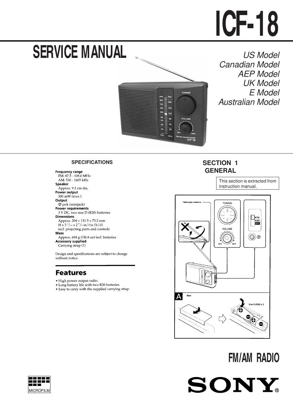
Sony icf 8 service manual

This is the 8 pages manual for sony icf 8 service manual.
Read or download the pdf for free. If you want to contribute, please mail your pdfs to info@audioservicemanuals.com.

Page: 1 / 8
left right
sony icf 8 service manual

Extracted text from sony icf 8 service manual (Ocr-read)


Page 1

Ð 2 Ð Note: Follow the disassembly procedure in the numerical order given. CABINET (REAR) SECTION 2 DISASSEMBLY KNOB (VOL), KNOB (TUNE) 1 Remove the battery case lid to direction of the arrow. 2 two screws (P 3 ´ 14) 4 cabinet (rear) 6 lug 5 screw (P 3 ´ 10) 3 three claws 1 two claws 1 two claws 2 knob (tune) 2 knob (vol) knob (tune) screw driverknob (vol) screw driver

Page 2

Ð 3 ÐÐ 4 Ð Note: Follow the assembly procedure in the numerical order given. SECTION 3 DIAL POINTER SETTING 1 Slide the pointer to the inner part. 2 Turn the VC gear fully in the arrow B direction. 3 Insert the pointer to the gear fitting the concave position of the pointer to the convex position of the gear. pointer A Note: When take off the pointer, remove to direction of the arrow A. B SECTION 4 ELECTRICAL ADJUSTMENTS [AM Section] Setting: Band select switch: AM0dB=1 µV [FM Section] Setting: Band select switch: FM Repeat the procedures in each adjustment several times, and the frequency coverage and tracking adjustments should be finally done by the trimmer capacitors. FM RF SSG ± 22.5 kHz frequency deviation by 400 Hz signal Output level: as low as possible +- level meter earphone jack set FM antenna terminal 8 W AM RF SSG 30% amplitude modulation by 400 Hz signal Output level: as low as possiblePut the lead-wire antenna close to the set. +- level mete r earphone jack set 8 W FM FREQUENCY COVERAGE ADJUSTMENT Adjust for a maximum reading on level meter. L3 75.0 MHz CT1 109.5 MHz FM TRACKING ADJUSTMENT Adjust for a maximum reading on level meter. L2 75.0 MHz CT2 109.5 MHz AM FREQUENCY COVERAGE ADJUSTMENT Adjust for a maximum reading on level meter. L4 520 kHz CT3 1,650 kHz AM TRACKING ADJUSTMENT Adjust for a maximum reading on level meter. L1 600 kHz CT4 1,400 kHz AM IF ADJUSTMENT Adjust for a maximum reading on level meter. T1 455 kHz Adjustment Location: MAIN board (Component Side) AM FREQUENCY COVERAGE CT3 L4 CT1 L3FM FREQUENCY COVERAGE FM antenna terminal L1 CT4 AM TRACKING T1 AM IF L2 CT2 FM TRACKINGIC1 S1 (BAND SELECT ) SWITCH FM«AM «OFF JW4