Sony icf 600 r service manual

This is the 12 pages manual for sony icf 600 r service manual.
Read or download the pdf for free. If you want to contribute, please mail your pdfs to info@audioservicemanuals.com.

Page: 1 / 12
left right
sony icf 600 r service manual

Extracted text from sony icf 600 r service manual (Ocr-read)


Page 1

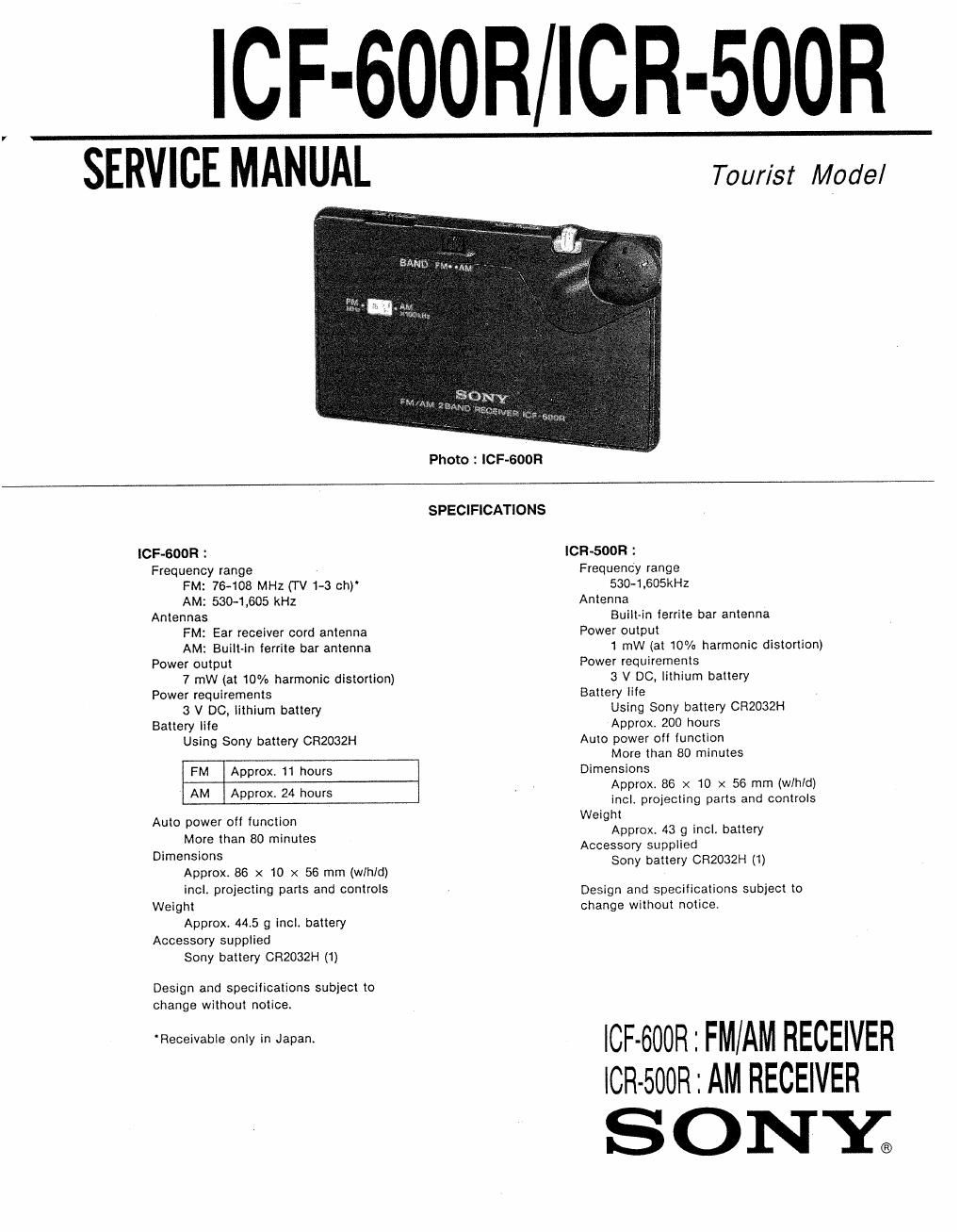
ICF-600RICR-500R

SERVICE MANUAL

Tour/st Model

Photo : ICF-GOOR

SPECIFICATIONS

ICF-GOOR :

Frequency range
FM: 76-108 MHz (TV1-3 ch)
AM: sac-1,605 kHz
Antennas
FM: Ear receiver cord antenna
AM: Built-in ferrite bar antenna
Power output
7 mW (at 10% harmonic distortion)
Power requirements
3 V DC, lithium battery
Battery life
Using Sony battery CR2032H

FM Approx, 11 hours
AM Approx, 24 hours

Auto power off function

More than 80 minutes
Dimensions

Approx. 86 x 10 x 56 mm (th/d)

incl. projecting parts and controls
Weight

Approx. 445 9 incl. battery
Accessory supplied

Sony battery CRZOBZH (1)

Design and specifications subject to
change without notice.

Receivable only in Japan.

ICR-SOOR :
Frequency range
530-1,605kHz
Antenna
Built~in lerrite bar antenna
Power output
1 mW (at 10% harmonic distortion)
Power requirements
3 V DC, lithium battery
Battery life
Using Sony battery CR2032H
Approx. 200 hours
Auto power off lunclion
More than 80 minutes
Dimensions
Approx. 86 x 10 x 56 mm (wlhld)
incl. projecting parts and controls
Weight
Approx. 43 9 incl. battery
Accessory supplied
Sony battery CR2032H (1)

Design and specifications subject to
change without notice.

ICF-600R : FM/AM RECEIVER
lCR-500R : AM RECEIVER

SONY;

Page 2

lCF-600R/ICR-500R

IC F-600R

BAND SWITCH : AM

AM RF signal
PUI [he lead-wire

generator
antenna dose [0

@ M lhe set.
_@:=

400HI, 30%
AM modu/allon
Output level: as low as possible

FM SECTION

BAND SWITCH : FM

FM RF signal
generalor

0 Test Point
___£II:TT- (FM Mm

.10on, 30% FM modulation
Isquency dew'elron : 22.5kHz
Output level: as low possible

VTVM

m [21
% 1-41-
53
1-4-

earphone [ask

Adjustment Location : MAIN BOARD (Side A)

SECTION 1
ADJUSTMENTS

0 Repeat the procedures in each adjustment several times. and the
frequency coverage and tracking adjustments should be finally
done by the trimmer capacitors.

AM IF ADJUSTMENT
Adjust for a maximum reading on VTVM.
455 kHz

L7

AM FREQUENCY COVERAGE ADJUSTMENT
Adjust for a maximum reading on VTVM.

L5 520 kHz
CT4 1,650 kHz
AM TRACKING ADJUSTMENT
Adjust for a maximum reading on VTVM.
L1 520 kHz
CT] 1,650 kHz

FM FREQUENCY COVERAGE ADJUSTMENT
Adjust for a maximum reading on VTVM.

LA 75 MHz
CT3 1095 MHz
FM TRACKING ADJUSTMENT
Adjust for a maximum reading on VTVM.
L2 75 MHZ
CTZ l09 5 MHz

L
Capra Frequency eaverege ed/usrmem

\_f

AM Tracking Ll _l

l

@
@

Test Fain!

adjuslmenl cry I/


(FM ANT)

5%)
(=3

L7 AM IF adjustment

L2
crz } FM Tlackmg adjuslment

L4
on} FM Frequency coverage adjustment

_2i