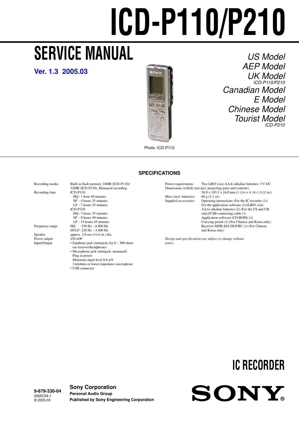
Sony icd p 110 service manual

This is the 32 pages manual for sony icd p 110 service manual.
Read or download the pdf for free. If you want to contribute, please mail your pdfs to info@audioservicemanuals.com.

Page: 1 / 32
left right
sony icd p 110 service manual

Extracted text from sony icd p 110 service manual (Ocr-read)


Page 2

3 ICD-P110/P210 SECTION 1 SERVICE NOTE 1-1. CAUTIONS OF FLASH MEMORY (IC701) EXCHANGE [Precaution When the Flash Memory (IC701) is Replaced] When the flash memory (IC701) is replaced, be sure to perform the BAD BLOCK check* and writing of the model code. If they are not completed, the unit will not operate normally. * BAD BLOCK check is to check the flash ROM memory area (the BAD BLOCK area) where data cannot be guaranteed. The resultant information of this check is stored in the TOC- AREA so that the BAD BLOCK area should not be used. [BAD BLOCK Check Procedure] 1. When the power is turned on after the flash memory (IC701) is replaced, the BAD BLOCK check starts automatically and the OPR (D701) lights in orange. 2. In about 30 seconds after start of the check, the OPR (D701) changes the color to green indicating that the check is completed. 1-2. NOTES FOR REPLACEMENT OF THE MICROCOMPUTER (IC702) The IC702 on the MAIN board has former and new types of models. Former type : MB91F233LLGA-GE1 (flash microcomputer) New type : MB91233LLGA-G-107E1 (mask microcomputer) The service parts include only new types of models. When replacing the IC702, check the model number. The transistors Q706 and Q707 for program write should be removed when the previous type is installed. MAIN BOARD (SIDE B) TP721 D701D701 OPR (PB) (REC) G R TP718 TP726 TP725 1 23 1 R730C708 ET701 Q704 R728R758 C729 C730 IC706 1-865-058-11 (11)