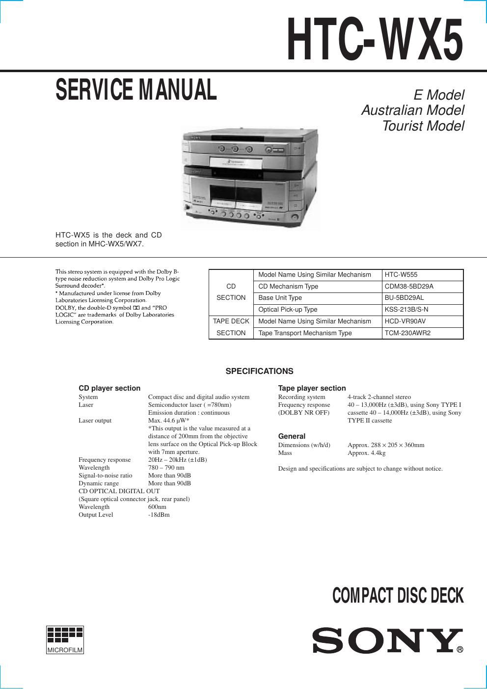
Sony htcwx 5 service manual

This is the 54 pages manual for sony htcwx 5 service manual.
Read or download the pdf for free. If you want to contribute, please mail your pdfs to info@audioservicemanuals.com.

Page: 1 / 54
left right
sony htcwx 5 service manual

Extracted text from sony htcwx 5 service manual (Ocr-read)


Page 2

3 TABLE OF CONTENTS 1. SERVICING NOTE .......................................................... 4 2. GENERAL .......................................................................... 7 3. DISASSEMBLY 3-1. Loading Panel ................................................................. 8 3-2. Back Panel and CD Mechanism Deck ............................ 8 3-3. Front Panel ...................................................................... 9 3-4. TC Mechanism Deck and Cassette Holder ..................... 9 3-5. Disc Tray ....................................................................... 10 4. MECHANICAL ADJUSTMENTS.......................... 11 5. ELECTRICAL ADJUSTMENTS ............................... 11 6. DIAGRAMS 6-1. Circuit Boards Location ................................................ 14 6-2. Block Diagrams ¥ CD Section ....................................................................... 15 ¥ Deck Section .................................................................... 16 ¥ Main Section .................................................................... 14 6-3. Printed Wiring Board CD Section .............................. 18 6-4. Schematic Diagram CD Section ................................ 19 6-5. Schematic Diagram Deck Section .............................. 20 6-6. Printed Wiring Board Deck Section ............................ 21 6-7. Printed Wiring Board Main Section ............................ 22 6-8. Schematic Diagram Main (1/2) Section ...................... 23 6-9. Schematic Diagram Main (2/2) Section ...................... 24 6-10. Printed Wiring Board Leaf SW Section .................... 25 6-11. Schematic Diagram Leaf SW Section ...................... 25 6-12. Printed Wiring Board Panel Section ......................... 26 6-13. Schematic Diagram Panel Section ............................ 27 6-14. Schematic Diagram CD Motor Section .................... 28 6-15. Printed Wiring Board CD Motor Section ................. 29 6-16. IC Block Diagrams ..................................................... 30 6-17. IC Pin Functions ......................................................... 32 7. EXPLODED VIEWS 7-1. Case and Back Panel Section ........................................ 39 7-2. Front Panel Section ....................................................... 40 7-3. CD Mechanism Section 1 (CDM38-5BD29A) ............. 41 7-4. CD Mechanism Section 2 (CDM38-5BD29A) ............. 42 7-5. Base Unit Section (BU-5BD29A) ................................. 43 7-6. TC Mechanism Section 1 (TCM230AWR2) ................ 44 7-8. TC Mechanism Section 2 (TCM230AWR2) ............... 45 8. ELECTRICAL PARTS LIST ........................................ 46