Sony htc h2800

This is the 57 pages manual for sony htc h2800.
Read or download the pdf for free. If you want to contribute, please mail your pdfs to info@audioservicemanuals.com.

Page: 1 / 57
left right
sony htc h2800

Extracted text from sony htc h2800 (Ocr-read)


Page 1

HTC-HZBOI)

SERVICE MANUAL AEP Model

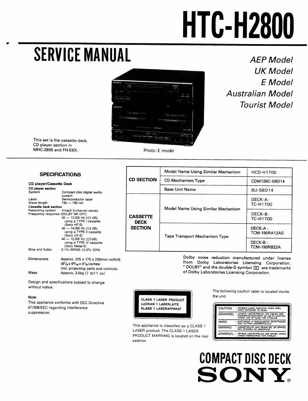
This set is the cassette deck,
CD player section in
MHC-ZBOO and FH~E6X.

UK Model

E Model
Australian Model
Tourist Model

Photo : E model

SPECIFICATIONS

CD playerICauette Deck
on puyor union

System Compact disc digital audio
sysrem

Laser Semiconductor laser

Wave length 780 - 790 nm

Call"!!! dldi Ioctlort
Recording system Minsk Z-channel siereo
Frequency response (DOLBY NR OFF)
40 -13.000 HZ (i3 dB),
using a TVPE I cassette
(Sony HFAS)
40 - .000 Hz [13 dB),
using a TVPE ll cassette
(Sony UX-S)
40-15000 HZ ItSdB),
using 3 TYPE l\l cassette
(Sony Metal»S)
Wow and lluiter 0.1% WRMS t0.3°/u (DIN)

Dimensions Approx. 225 x 175 x 230mm (w/h/d)
(87/9 x 69/; x 9]; inches)
incl. projecting parts and controls
Mass Approx. 3.5kg (7 |b1 1 oz)

Design and specifications subject to change
without notice

Note

This appliance conforms with EEC Directive
B7l308/EEC regarding interlerence
suppression.

Model Name Using Similar Mechanism HCD-H17OO

CD SECTION CD Mechanism Type CDM1SBC-SBD14
Base Unit Name BU-SBDM
DECK-A:
TC-Hi 700
Model Name Using Similar Mechanism
DECK-B:
CASSETTE TC-H 1 700
DECK
SECHON DECKA I

TCM-lSORAlZAS
Tape Transport Mechanism Type

DECK«B :
TCM~190H322A

Dolby noise reduction manufactured under license
from Dolby Laboratories Licensing Corporation.
" DOLBY" and the double-D symbol D0 are trademarks
of Dolby Laboratories Licensing Corporation

The following caution label is located inside
the unit.

CLASS 1 LASER PRODUCT

LUOKAN 1 LASEHLAITE

5mm m 5555,? W m

wwssn :r'weaeimueazeew om",
UNDGU uDsETY'ELSE ions

KLASS 1 LASERAPFARAT

vfi-fi-mm wAfiAassa M suouwmrus men-:55.
This appliance Is classified as a CLASS 1 VAR, 5 gmmfifaffwm m W

W m
LASER product. The CLASS 1 LASER w-

"DVAHSEL ~ 338%?me 250:: i 5'

PRODUCT MARKING is located on the rear

commcrmsc DECK
SONE

Page 2

TABLE OF CONTENTS

Section Elle Bag:
1. SERVICING NOTE
1-1. Supply of Power During Services ................... 3
1-2. Laser Note ...................................................... 3
1-3. How to Open the Disc Tray when Power Switch
Turns Off ........................................................ 3
2. GENERAL .................................... 4
3. DISASSEMBLY ............................................... 5
4. DIAGRAMS
4-1. Semiconductor Lead Layouts . 7
4-2. Waveforms .. 8
4-3. Circuit Boards Location .................................. 10
4-4. Schematic Diagram
(Panel/Power Supply Section) ........................ 1 1
4-5. lC Block Diagram
(Panel/Power Supply Section) ........................ 14
4-6. Printed Wiring Boards
(Panel/Power Supply Section) ........................ 15
4-7. Schematic Diagram (Deck Section)
~AEP, UK, EE, G, IT Model - ....................... 19
4-8. [0 Block Diagram (Deck Section)
-AEP, UK, EE, G, IT Model - ....................... 22
4-9. Printed Vifiring Boards (Deck Section)
- AEP, UK, EE, G. IT Model - ....................... 23
4-10. Printed Wiring Boards (Deck Secfion)
- E, EA, AUS, JE Model - .............................. 27
4-11. Schematic Diagram (Deck Section)
- E, EA, AUS, JE Model - .............................. 31
4-12. IC Block Diagram (Deck Section)
- E, EA, AUS, JE Model - ................ 34
4-13. IC Block Diagram (CD Section) ..... 35
4-14. Schematic Diagram (CD Section) . 36
4-15. Printed Wiring Boards (CD Section) ............... 39
4-16. Printed Wiring Boards (Tape MD Section)... 42
4-17. Schematic Diagram (Tape MD Section) ...... 45

SAFETY-RELATED COMPONENT WARNINGII

COMPONENTS IDENTIFIED BY MARK A OR DOTTED LINE
WITH MARK A ON THE SCHEMATIC DIAGRAMS AND IN
THE PARTS LIST ARE CRITICAL TO SAFE OPERATION. REPLACE
THESE COMPONENTS WITH SONY PARTS WHOSE PART
NUMBERS APPEAR AS SHOWN IN THIS MANUAL OR IN
SUPPLEMENTS PUBLISHED BY SONY.

519mm Lille Rage
5. EXPLODED VIEWS
5-1. Front Panel Section ........................................ 47
5-2. Chassis Section .............
5-3. Cassette Deck Section ..
5-4. CD Mechanism Section .................................. 50
5-5. CD Base Unit Section ..............
5-6. Cassette Mechanism Section-1
5-7. Cassette Mechanism Section-2...
6. ELECTRICAL PARTS LIST ............................ 54

SUPPLEMENT-1

NOTE
E E

IT

EA
AUS 2
JE

: East European
: German

: Italian

: Saudi Arabia

Australian

: Tourist