Sony htc d 209 service manual

This is the 33 pages manual for sony htc d 209 service manual.
Read or download the pdf for free. If you want to contribute, please mail your pdfs to info@audioservicemanuals.com.

Page: 1 / 33
left right
sony htc d 209 service manual

Extracted text from sony htc d 209 service manual (Ocr-read)


Page 1

HTC-DZUQ/D309

SERVICE MANUAL AEP Model

UK Model
E Model
Australian Model

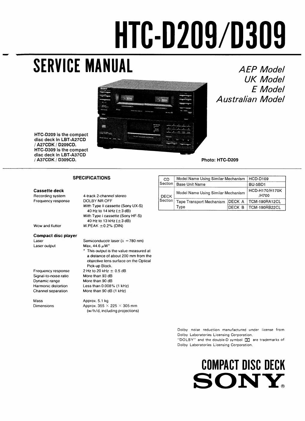
HTC-D209 Is the compact
disc deck ln LBT-A27CD
l A27CDK/ DzoscD.
HTC-DaoQ Is the compact
disc deck In LBT-A37CD

/ A37CDK / DSOSCD. Photo: HTC-D209

SPECIFICATIONS CD Model Name Using Similar Mechanism HCD-D109
590110 Base Unit Name BU-SBDI
Cassette deck . . . . HCD-H170/H170K
Recording system 4-track 2-channel stereo DECK Model Name Usmg Similar MQChamsm /H700
Frequency response DQLBY NR OFF Section Tape Transport Mechanism DECK A TCM-190FIA12CL
with Type II cassette (Sony UX-Sl Type DECK B TCMJQORBZZCL

40 Hz to 4 kHz (:3 dB)
With Type l cassette (Sony HF-S)
40 Hz to 13 kHz (:3 (18)

Wow and flutter WPEAK 10.2% (DIN)
Compact disc player

Laser Semiconducotr laser (A = 780 nm)
Laser output Max, 44.6 #W'

' This output is the value measured at
a distance oi about 200 mm from the
objective lens surface on the Optical

Pick-up Block.
Frequency response 2 Hz to 20 kHz 1 0.5 dB
SignaHonorse ratio More than 93 dB
Dynamic range More than 90 dB
Harmonic dlSIOflIOn Less than 0.008% (1 kHz)
Channel separation More than 90 dB (1 kHz)
Mass Approx. 5.1 kg
Dimensions Approx. 355 x 225 X 305 mm

(w/h/d. including projections)

Dolby noise reduction manufactured under license from
Dolby Laboratories Licensing Corporation.
"DOLBY" and the double-D symbol DU are trademarks of
Dolby Laboratories Licensing Corporation.

summer nisc DECK
SONY.

Page 2

This appliance is classilied as 3 CLASS 1 LASER product.

The CLASS 1 LASER PRODUCT MARKING is located on
the rear exterior.

CLASS 1 LASER PRODUCT

LUOKAN I LASERLMTE
KLASS I LASERAPPARAT

Laser component in this product is capable of emitting
radiation exceeding the limit for Class 1.

The lollowing caution label is located inside the unit,

; INVISIBLE use; RADIAYION ween oven
AVOID Exvosun: m BEA M

ustLiG uszaswluma van ABNINE NA:
SIKKEHHE osAraevcEa: an no: Ar :uwmon
UNDGA uns (was: we svnAiwo

; AvaszA JA SUOJALUKIVUS ONIIEIIAESSA
my Amiim usznsnsimtz

: assaswnwe NA: Drum on An oevNAo
ocu stansw A: Ufixovvu

CAUTION
ADVARSEL -

VARO!
VAR N ING

usmuo uszasmALme NA: nsxsst APMES
uMNsA Exsvoneems Von smALEN

ADVARSEL .

NOTES ON HANDLING THE OPTICAL PICK-
UP BLOCK OR BASE UNIT

The laser diode in the optical pick-up block may
suffer electrostatic breakdown because of the poten-
tial difference generated by the charged electrostatic
load, etc. on clothing and the human body.

During repair, pay attention to electrostatic break-
down and also use the procedure in the printed
matter which is included in the repair parts.

The flexible boardis easily damaged and should be
handled with care.

NOTES ON LASER DIODE EMISSION CHECK

The laser beam on this model is concentrated so
as to be focused on the disc reflective surface by the
objective lens in the optical pick-up block. There-
fore, when checking the laser diode emission, observe
more than 30 cm away from the objective lens.

SAFETY- RELATED COMPONENT WARNING

COMPONENTS IDENTIFIED BY MARK A 0R DOTTED
LINE WITH MARK A ON THE SCHEMATIC DIAGRAMS
AND IN THE PARTS LIST ARE CRITICAL TO SAFE
OPERATION. REPLACE THESE COMPONENTS WITH
SONY PARTS WHOSE PART NUMBERS APPEAR AS
SHOWN IN THIS MANUAL OR IN SUPPLEMENTS PUB-
LISHED BY SONY.

TABLE OF CONTENTS

Section Title Page
Specifications .................................. 1
Notes on Handling the Optical Pick-up Block

or Base Unit ................................... 2

Notes on Laser Diode Emission Check 2
1_ GENERAL ............... . ............. 3
2. ADJUSTMENTS
2-1. Mechanical Adjustments . ~ ~ 4
22. Electrical Adjustments 4
Cassette Deck Section ----- 4
CD Section .............................. 7
3. DIAGRAMS
3-]. CD Section Block Diagram ~~~~~~~~~~~ 9
3-2. Cassette Deck Section Block Diagram - - - 11
3-3 CD Section Printed Wiring Boards 14
3-4. CD Section Schematic Diagram ~ ~ ~ ' 17
3-5. Cassette Deck Section Schematic Diagram - ~ - ~ 22
3-6 Cassette Deck Section Printed Wiring Boards - - 27
4. EXPLODED VIEWS -------------------- 31
5. ELECTRICAL PARTS LIST ------------ 37

MODEL IDENTIFICATION

A 4-955731 9.01:

Back Panel

HTC-DZOQ AEP, UK. Italian. Germany Mdels.

HTC-D209 E. East European. Malaysia.
Singapore Models.

HTC-0209 Saudi Arabia, Australian Models.

HTC-D309 AEP. UK. Italian. Germany Models.

HTc-Daos E, East European. Malaysia,
Singapore. Cls Models.

HTC-D309 Saudi Arabia, Australian Models.

4»955-819-11:
4955-31941:
4-955-81 9-312
4355-81941:

4-955-81 9-51: