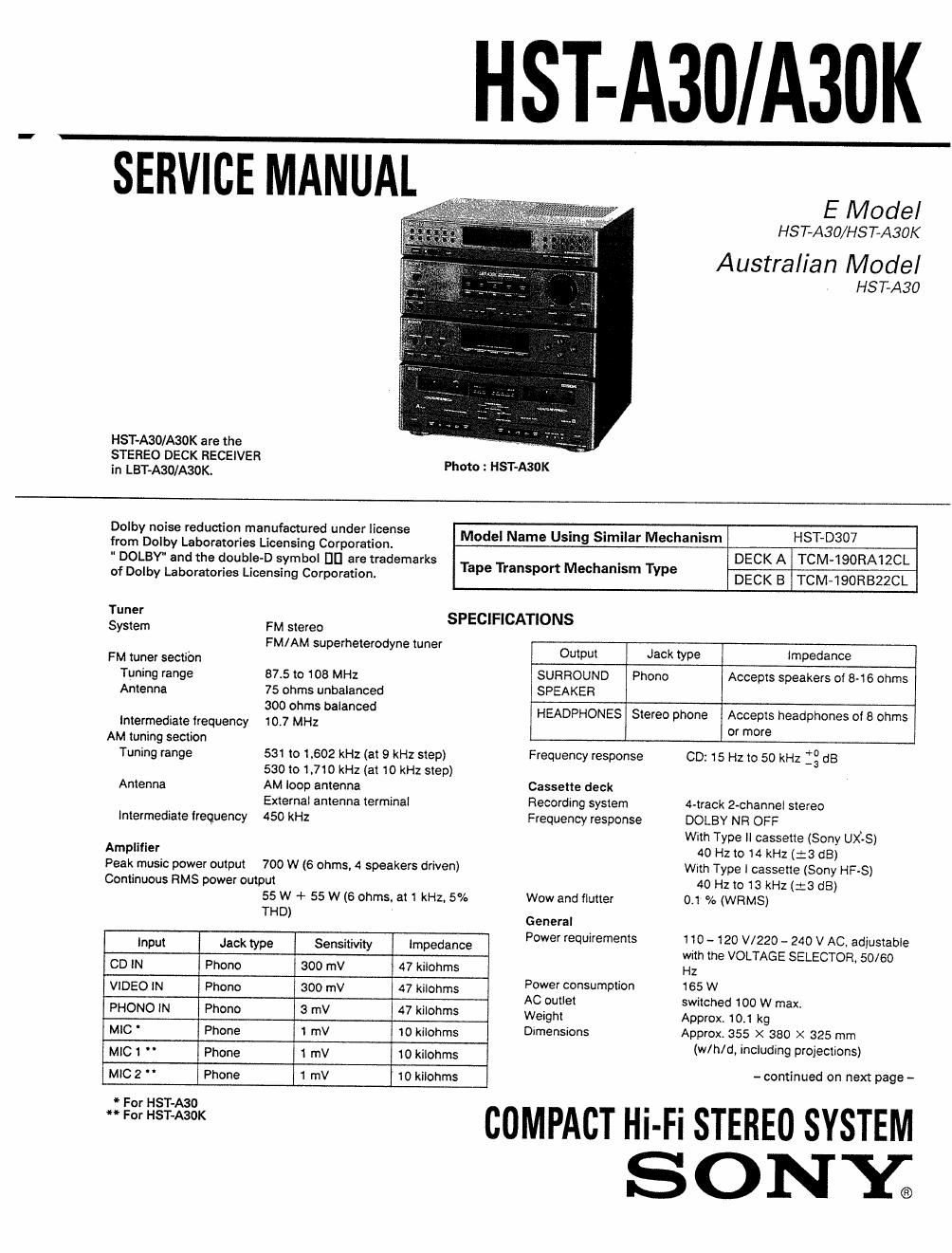
Sony hstz 30 service manual

This is the 46 pages manual for sony hstz 30 service manual.
Read or download the pdf for free. If you want to contribute, please mail your pdfs to info@audioservicemanuals.com.

Page: 1 / 46
left right
sony hstz 30 service manual

Extracted text from sony hstz 30 service manual (Ocr-read)


Page 2

i
HST-A30/A30K

Turntable (only (or Latin American and Austrafian models)

Platter 30 cm

Tone arm type Dynamically balanced
Cartridge type Moving magnet type

Stylus (IN-234 (06 mil diamond)
Weight Approx 2.3 kg

Dimensions Approx. 355 X 95 X 345 mm

(w/h/d. including projections)

Speaker system (SS-D33)

Speaker system 3 way. 16 ohms
Weight Approx. 6.8 kg per speaker
Dimensions Approx. 280 X 480 X 245 mm

(w/h/d. including projections)

Supplied accessories

45-mm adaptor (1) (only for Latin American and Australian models)
Remote commander RM-SSOS (1)

FM wire antenna (1)

AM loop antenna (1)

Batteries Sony SUM-3 (NS) (2)

Speaker cord (2)

Microphone (1) (only for LBT-A3OK)

Design and specifications are subject to change without notice,

MODEL IDENTIFICATION
- SPECIFICA110N LABEL -
H$T-A30
HST-A30K
i
SONY; MODEL NO. W
W

V~ 0H2 1 5W

El

SERIAL Moi
VlllllllllA

HST-A30 E Model

HST-A30 Australian Model
HST-A30K Saudi Arabia Model .
HST-A30K E Model, MALAYSIA Model :

: SONY CORP

: MADE IN MALAYSIA
' MADE IN JAPAN
SONY CORP

TABLE OF CONTENTS
$9M! Eli Eage
1. GENERAL
1-1I Location of Controls ....................................... 3
2. ADJUSTMENTS
2-1. Mechanical Adjustments ................................ 5
2-2. Electrical Adjustments ................ , ................... 5
3. DIAGRAMS
3-1. Circuit Boards Location . a 10
3-2. Block Diagrams 11
3-3. to Block Diagrams i. . 13
3-4. Semiconductor Lead Layouts ......................... 15
3-5. Printed Wiring Boards (TC Section) .. . 16
3-6. Schematic Diagram (TC Section) 19
3-7. Printed Wiring Boards (Main Section) .. . 24
3-8. Schematic Diagram (Main Section) ................ 29
3.9. Printed Wiring Boards (Panel Section). .. 34
3-10. Schematic Diagram (Panel Section) . 39
3-11. Printed Wiring Boards (Echo Section) .. .. 48
3-12. Schematic Diagram (Echo Section) ............... 45
4. EXPLODED VIEWS
44. Cabinet Section .............................................. 47
4-2. Front Panel Section .......... 48
43. Mechanism Deck Section 1 .. 49
4-4. Mechanism Deck Section 2.. .. 50
4-5. Mechanism Deck Section 3 ............................ 51
5. ELECTRICAL PARTS LIST ............................ 52

SAFETY-RELATED COMPONENT WARNINGII

COMPONENTS IDENTIFIED BY MARK A OR DOTTED LINE
WITH MARK A ON THE SCHEMATIC DIAGRAMS AND IN
THE PARTS LIST ARE CRITICAL TO SAFE OPERATION. REPLACE
THESE COMPONENTS WITH SONY PARTS WHOSE PART
NUMBERS APPEAR AS SHOWN IN THIS MANUAL OR IN
SUPPLEMENTS PUBLISHED BY SONY.