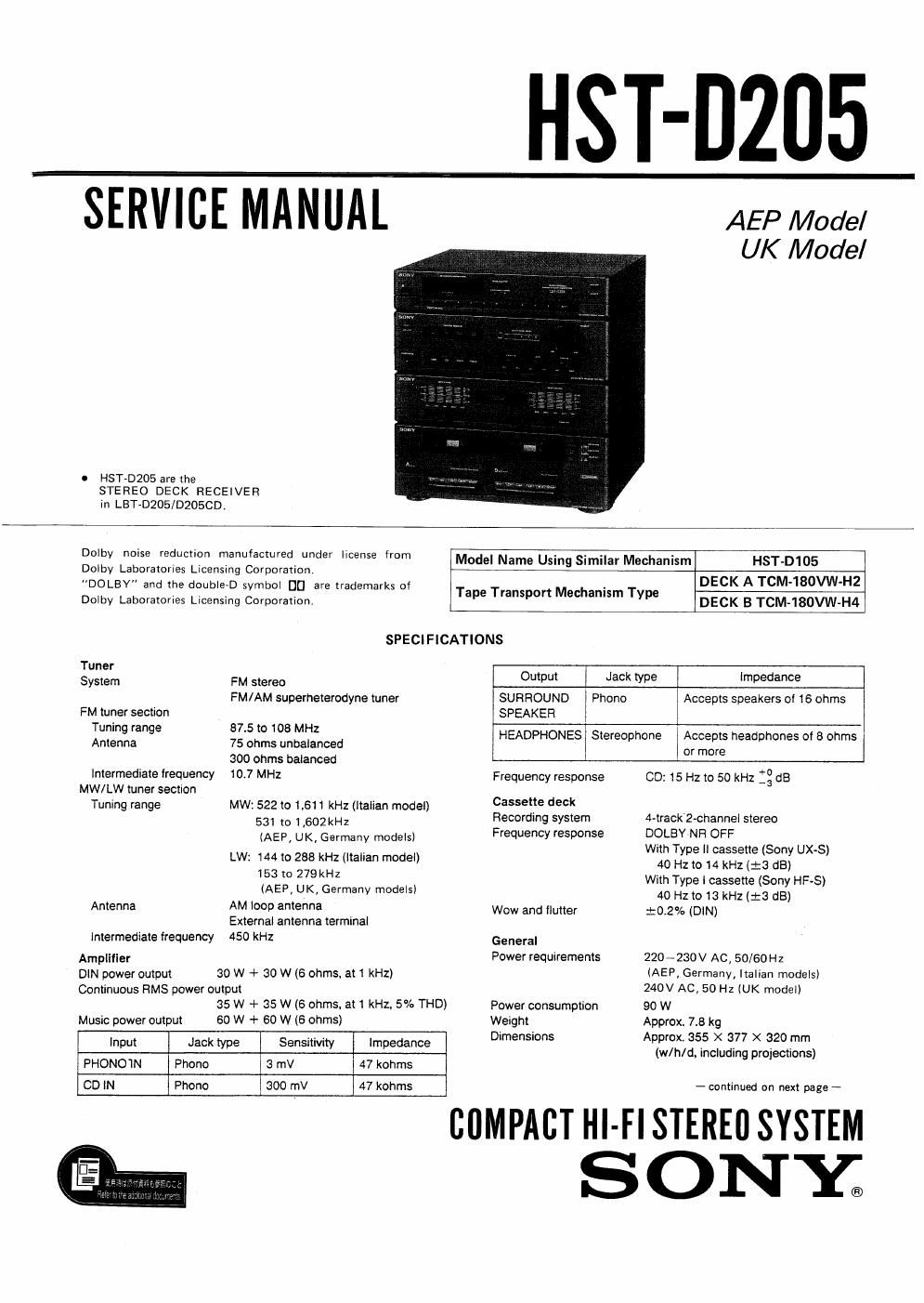
Sony hstd 205 service manual

This is the 29 pages manual for sony hstd 205 service manual.
Read or download the pdf for free. If you want to contribute, please mail your pdfs to info@audioservicemanuals.com.

Page: 1 / 29
left right
sony hstd 205 service manual

Extracted text from sony hstd 205 service manual (Ocr-read)


Page 1

HST-0205

SERVICE MfiUAL AAAAAAAA

UK Model

n HST-D205 are the
STEREO DECK RECEIVER
in LBT-DZOS/DZOSCD.

Dolby noise reduction manufactured under license from Model Name Using Similar Mechanism HST-D105

Dolby Laboratories Licensing Corporation.
"DOLBY" and the double-D symbol UL] are trademarks of Tape Transport Mechanism Type DECK A TCM180VW'H2

Dolby Laboratories Licensing Corporation. DECK B TCM-180VW-H4

SPECIFICATIONS

Tuner

System FM stereo Output Jack type Impedance
FM/AM superheterodyne tuner SURROUND Phono Accepts speakers of 16 ohms
FM tuner section SPEAKER
Tuning range 87.5 to 108 MHZ HEADPHONES Siereophone Accepts headphones of 5 ohms
Antenna 75 ohms unbalanced or more
300 ohms balanced
Intermediate frequency 107 MHZ Frequency response CD: 15 Hz to 50 kHz :3 dB
MW/LW tuner section
Tuning range MW: 522 to 1,611 kHz (Italian model) cassefle 5 ,
531 to 1 502. Recording system 4-track 2-channel stereo
(AEP, UK, Germany models) Frequency response DQLBY NR OFF
. With Type II cassette (Sony UX-S)
LW: 144 to 238 kHz (Italian model) 40 HZ to 14 kHz (:3 dB)
153 m 279 kHz With Type | cassette (Sony HF-S)
IAEP, UK, Germany models) 40 Hzt013 kHz (:3 dB)
Antenna AM I009 amen Wow and flutter :o.2% (DIN)
External antenna terminal
Intermediate frequency 450 kHz General
Amplifier Power requirements 220 ~230 V AC, 50/60Hz
DIN power output 30 W + 30 W (6 ohms, at 1 kHz) (AEP, Germany, Italian models)
Continuous FlMS power output 240V Ac, 50 Hz (UK model)
35 W + 35 W (5 ohms. at 1 kHz. 5% THD) Power consumption 90 W
Music power output 60 W + 60 W (6 ohms) Weight Approx. 7.8 kg
Input Jack type Sensitivity Impedance Dimensmns flax/355311;; :gigtgg)
PHONO'IN Phone 3 mV 47 kohms
CD IN Phone 300 mV 47 kohms - continued on next page ~

cuMPAci Hl-FlSTEREflSYSTEM
SONYa

Page 2

HST-D205

Supplied accessories

Remote commander RM-S130 (1)
FM wire antenna (1)

AM Ioop antenna (1)

Batteries Sony SUM-3 (NS)(2)

Design and specifications subiect to change without notlce.

Note
Thus appliance conforms with EEC Directives 87/308/ EEC
regarding interference suppression

MODEL IDENTIFICATION
-Specification Label-

SONYa MODEL N0. HST-D205
-

STEREO DECK RECEIVER

WA

SERIAL NOi
ASSEMBLED IN MALAYSIA

AEP, Germany, Italian Model: AC: 220V-230V~50/60H2
UK Model: AC: 240V~50Hz

Title

TABLE OF CONTENTS

Section Page

SECTION 1. GENERAL

1-1.

Location of Controls ------------------- 3

SECTION 2. ADJUSTMENTS

21.
2-2.

Mechanical Adjustments ---------------- 4
Electrical Adjustments ----------------- 4

SECTION 3. DIAGRAMS

3-1.


Block Diagram .......................... 7
. IC Block Diagrams - 9
. Semiconductor Lead Layouts ' 11
. Circuit Boards Location ~~~~~~~~~~ ' ll
. Printed Wiring Boards (TC Section) -- l3
. Schematic Diagram (TC Section) ~ 15

. Schematic Diagram (Main Section) ------ 19
. Printed Wiring Boards (Main Section) ~ -- 23

SECTION 4. EXPLODED VIEWS

4-1, Cabinet Section ....................... 27
4-2. Front Panel Section ------------------- 23
4-3. Mechanism Deck Section (1) ------------- 29
4-4. Mechanism Deck Section (2) ------------- 30
4-5. Mechanism Deck Section (3) ------------- 31
SECTION 5. ELECTRICAL PARTS LIST """"" 32

SAFETY-R E LATED COMPONENT WARNI NGII

COMPONENTS IDENTIFIED BY MARK & 0R DOTTED
LINE WITH MARK A ON THE SCHEMATIC DIAGRAMS
AND IN THE PARTS LIST ARE CRITICAL TO SAFE
OPERATION. REPLACE THESE COMPONENTS WITH
SONY PARTS WHOSE PART NUMBERS APPEAR AS
SHOWN IN THIS MANUAL OR IN SUPPLEMENTS PUB-
LISHED BY SONY.