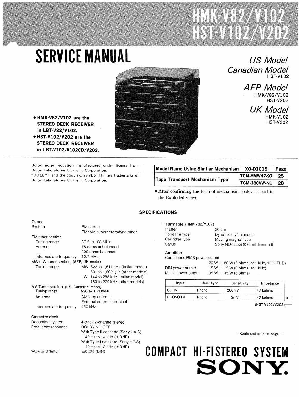
Sony hmk v 82 service manual

This is the 45 pages manual for sony hmk v 82 service manual.
Read or download the pdf for free. If you want to contribute, please mail your pdfs to info@audioservicemanuals.com.

Page: 1 / 45
left right
sony hmk v 82 service manual

Extracted text from sony hmk v 82 service manual (Ocr-read)


Page 2

HMK-V82/V102
HST-V102/V202

TABLE OF CONTENTS


Output Jack type Voltage Impedance
SURROUND Phono Accepts speakers ol81016 . .
SPEAKER ohms M m Page
HEADPHONES ~Stereophone Accepls headphones of 8 ohms
or more 1. GENERAL
1-1. Location of Controls ............................. 3
Frequency response CD: 15 Hz to 50 kHz :3 dB
General 2. ADJUSTMENTS
Power requirements 120V AC, 60Hz (US Canadian model) 2'1- Mechanical Adjustments ~
220V AC, 50H: (AEP model) 2-2. Electrical Adjustments ............................ 4
240V AC, 50Hz (UK model)
Power consumption 60W (US, AEP model)
now (UK model) 3- DIAGRAMS
Weight Approx 7kg (HMK~V82/V102) 3-1. Semiconductor Lead Layout ...................... 7
Approx 6kg (HST-V102/V202) 32 IC Block Diagrams .............................. 7
Dimensions Approx 355x377><325 mm .
(HMK-V82/V102) 3 3, Block Diagram .................................. 8
Approx. 355x290x325 mm 3-4. Printed Wiring Boards .......
(HST-V102/V202) 3-5 Schematic Diagram Tuner Section ..............
(w/h/d, '"dudmg p°°°t'°"s) 3v6. Schematic Diagram Main Section ................ 19
Design and specifications subject to change without notice. 4 EXPLODED VIEWS
Note 4-1. Cabinet Section .................................. 23
This appliance conforms with EEC Directives 87/308/EEC 4-2. Front Panel Section
gelding interierence SUPp'eSSi°~ 4-3. Mechanism Deck Se ion (1) ......................

4-4. Mechanism Deck Section (2) . i .
4v5i Mechanism Deck Section (3) . . .
4~6. Mechanism Deck Section (4) . .. ................ 28


4-7. Mechanism Deck Section (5) ...................... 29
4-8. Mechanism Deck Section (6)} . , . .......... 30
49, Player Section .......... 31
5. ELECTRICAL PARTS LIST ...................... 32

SUPPLEMENT-1

SAFETY-RELATED COMPONENT WARNING! !

COMPONENTS IDENTIFIED BV MARK A 0R DOTTED
LINE WITH MARK A ON THE SCHEMATIC DIAGRAMS
AND IN THE PARTS LIST ARE CRITICAL TO SAFE
OPERATION. REPLACE THESE COMPONENTS WITH
SONV PARTS WHOSE PART NUMBERS APPEAR AS
SHOWN IN THIS MANUAL OR IN SUPPLEMENTS PUB-
LISHED BV SONY.