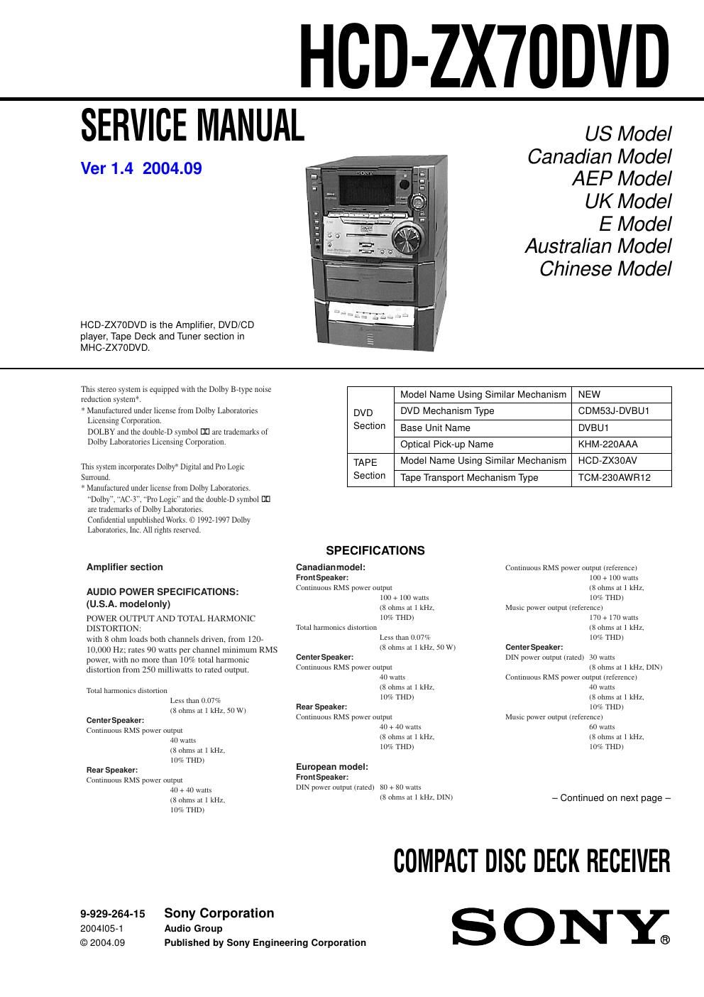
Sony hcd zx 70dvd

This is the 136 pages manual for sony hcd zx 70dvd.
Read or download the pdf for free. If you want to contribute, please mail your pdfs to info@audioservicemanuals.com.

Page: 1 / 136
left right
sony hcd zx 70dvd

Extracted text from sony hcd zx 70dvd (Ocr-read)


Page 1

2 Inputs VIDEO (AUDIO) IN: voltage 250 mV, (phono jacks) impedance 47 kilohms MD IN: voltage 450 mV, (phono jacks) impedance 47 kilohms MIC: sensitivity 1 mV, (mini jack) impedance 10 kilohms (Asian model only) Outputs MD OUT: voltage 250 mV (phono jacks) impedance 1 kilohms VIDEO OUT: max. output level (phono jack) 1Vp-p, unbalanced, Sync negative, load impedance 75 ohms S-VIDEO OUT: Y: 1Vp-p, unbalanced, (4-pin/mini-DIN jack) Sync negative, C: 0.286Vp-p, load impedance 75 ohms PHONES: accepts headphones of (stereo mini jack) 8 ohms or more FRONT SPEAKER: accepts impedance of 8 to 16 ohms REAR SPEAKER: accepts impedance of 8 to 16 ohms CENTER SPEAKER: accepts impedance of 8 to 16 ohms WOOFER OUT: Voltage 1 V, impedance 1 kilohms DVD player section Laser Semiconductor laser Frequency response DVD (PCM 48 kHz): 2 Hz -“ 22 kHz = (Β±1 dB) CD: 2Hz -“ 20 kHz = (Β±1 dB) Signal-to-noise ratio More than 90 dB Dynamic range More than 90 dB Video color system format NTSC, PAL DIGITAL OUT OPTICAL (Square optical connector jack, rear panel) Wavelength 660 nm Output Level-“18 dBm Tape player section Recording system 4-track 2-channel stereo Frequency response 40 -“ 13,000 Hz (Β±3 dB), (DOLBY NR OFF) using Sony TYPE I cassette 40 -“ 14,000 Hz (Β±3 dB), using Sony TYPE II cassette Tuner section FM stereo, FM/AM superheterodyne tuner FM tuner sectionTuning range North American model: 87.5 -“ 108.0 MHz (100 kHz step) Other models: 87.5 -“ 108.0 MHz (50 kHz step) Antenna FM antenna Antenna terminals 75 ohm unbalanced Intermediate frequency 10.7 MHz AM tuner sectionTuning range North American model: 530 -“ 1,710 kHz (with the interval set at 10 kHz) 531 -“ 1,710 kHz (with the interval set at 9 kHz) European and Middle Eastern models: 531 -“ 1,602 kHz (with the interval set at 9 kHz) Other models: 531 -“ 1,602 kHz (with the interval set at 9 kHz) 530 -“ 1,710 kHz (with the interval set at 10 kHz) Antenna AM loop antenna Antenna terminals External antenna terminal Intermediate frequency 450 kHz Music power output (reference) 60 + 60 watts (8 ohms at 1 kHz, 10% THD) Other models:The following measured at AC 120/220/240 V, 50/60 Hz Front Speaker: DIN power output (rated) 95 + 95 watts (8 ohms at 1 kHz, DIN) Continuous RMS power output (reference) 120 + 120 watts (8 ohms at 1 kHz, 10% THD) Center Speaker: DIN power output (rated) 30 watts (8 ohms at 1 kHz, DIN) Continuous RMS power output (reference) 40 watts (8 ohms at 1 kHz, 10% THD) Rear Speaker: DIN power output (rated) 30 + 30 watts (8 ohms at 1 kHz, DIN) Continuous RMS power output (reference) 40 + 40 watts (8 ohms at 1 kHz, 10% THD) General Power requirements North American model: 120 V AC, 60 Hz European model: 230 V AC, 50/60 Hz Australian model: 230 -“ 240 V AC, 50/60 Hz Mexican model: 120 V AC, 60 Hz Thai and Chinese models: 220 V AC, 50/60 Hz Other models: 120 V, 220 V or 230 -“ 240 V AC, 50/60 Hz Adjustable with voltage selector Power consumption North American model: 220 watts European model: 220 watts Other models: 230 watts Dimensions (w/h/d) Approx. 250 x 375 x 395 mm Mass North American model: Approx. 13.2 kg European model: Approx. 13.0 kg Other models: Approx. 13.5 kg Design and specifications are subject to change without notice. Rear Speaker: DIN power output (rated) 30 + 30 watts (8 ohms at 1 kHz, DIN) Continuous RMS power output (reference) 40 + 40 watts (8 ohms at 1 kHz, 10% THD)

Page 2

3 1. SERVICING NOTES ............................................... 5 2. GENERAL ................................................................... 7 3. DISASSEMBLY ......................................................... 9 4. ASSEMBLY ................................................................. 18 5. MECHANICAL ADJUSTMENT .......................... 21 6. DIAGRAMS 6-1. Note for Printed Wiring Boards and Schematic Diagrams ....................................................... 23 6-2. Printed Wiring Board -“ TK Board -“............................... 24 6-3. Schematic Diagram -“ TK Board -“................................. 25 6-4. Printed Wiring Board -“ MB Board (Side A) -“............... 26 6-5. Printed Wiring Board -“ MB Board (Side B) -“............... 27 6-6. Schematic Diagram -“ MB Board (1/10) -“...................... 28 6-7. Schematic Diagram -“ MB Board (2/10) -“...................... 29 6-8. Schematic Diagram -“ MB Board (3/10) -“...................... 30 6-9. Schematic Diagram -“ MB Board (4/10) -“...................... 31 6-10. Schematic Diagram -“ MB Board (5/10) -“...................... 32 6-11. Schematic Diagram -“ MB Board (6/10) -“...................... 33 6-12. Schematic Diagram -“ MB Board (7/10) -“...................... 34 6-13. Schematic Diagram -“ MB Board (8/10) -“...................... 35 6-14. Schematic Diagram -“ MB Board (9/10) -“...................... 36 6-15. Schematic Diagram -“ MB Board (10/10) -“................... 37 6-16. Printed Wiring Board -“ IF Board -“................................ 38 6-17. Schematic Diagram -“ IF Board -“................................... 39 6-18. Printed Wiring Boards -“ CDM Section -“....................... 40 6-19. Schematic Diagram -“ CDM Section -“........................... 41 6-20. Printed Wiring Board -“ AUDIO Board -“....................... 42 6-21. Schematic Diagram -“ AUDIO Board -“.......................... 43 6-22. Printed Wiring Board -“ LEAF SW Board -“................... 44 6-23. Schematic Diagram -“ LEAF SW Board -“...................... 44 6-24. Printed Wiring Board -“ MAIN Board -“......................... 45 6-25. Schematic Diagram -“ MAIN Board (1/5) -“................... 46 6-26. Schematic Diagram -“ MAIN Board (2/5) -“................... 47 6-27. Schematic Diagram -“ MAIN Board (3/5) -“................... 48 6-28. Schematic Diagram -“ MAIN Board (4/5) -“................... 49 6-29. Schematic Diagram -“ MAIN Board (5/5) -“................... 50 6-30. Printed Wiring Board -“ MIC Board -“............................ 51 TABLE OF CONTENTS ATTENTION AU COMPOSANT AYANT RAPPORT Γ- LA SΓ‰CURITΓ‰! LES COMPOSANTS IDENTIFIΓ‰S PAR UNE MARQUE 0 SUR LES DIAGRAMMES SCHΓ‰MATIQUES ET LA LISTE DES PIÈCES SONT CRITIQUES POUR LA SΓ‰CURITΓ‰ DE FONCTIONNEMENT. NE REMPLACER CES COM- POSANTS QUE PAR DES PIÈCES SONY DONT LES NUMΓ‰ROS SONT DONNΓ‰S DANS CE MANUEL OU DANS LES SUPPLΓ‰MENTS PUBLIΓ‰S PAR SONY. SAFETY-RELATED COMPONENT WARNING!! COMPONENTS IDENTIFIED BY MARK 0 OR DOTTED LINE WITH MARK 0 ON THE SCHEMATIC DIAGRAMS AND IN THE PARTS LIST ARE CRITICAL TO SAFE OPERATION. REPLACE THESE COMPONENTS WITH SONY PARTS WHOSE PART NUMBERS APPEAR AS SHOWN IN THIS MANUAL OR IN SUPPLEMENTS PUB- LISHED BY SONY. 6-31. Schematic Diagram -“ MIC Board -“............................... 51 6-32. Printed Wiring Boards -“ FRONT AMP/HP Boards -“.... 52 6-33. Schematic Diagram -“ FRONT AMP/HP Boards -“........ 53 6-34. Printed Wiring Board -“ SURR AMP Board -“................ 54 6-35. Schematic Diagram -“ SURR AMP Board -“................... 55 6-36. Printed Wiring Boards -“ PANEL/CD SW Boards -“...... 56 6-37. Schematic Diagram -“ PANEL/CD SW Boards -“........... 57 6-38. Printed Wiring Board -“ SUB PANEL Board -“.............. 58 6-39. Schematic Diagram -“ SUB PANEL Board -“................. 59 6-40. Printed Wiring Boards -“ TRANS/SUB TRANS Boards -“.................................. 60 6-41. Schematic Diagram -“ TRANS/SUB TRANS Boards -“.................................. 61 7. EXPLODED VIEWS ................................................ 65 8. ELECTRICAL PARTS LIST ............................... 73