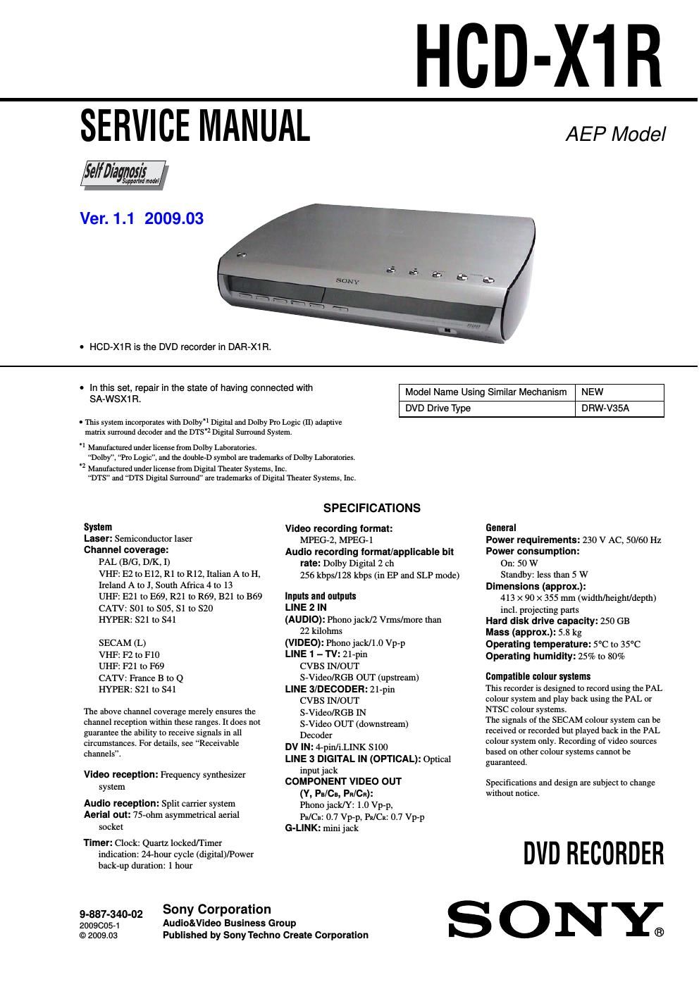
Sony hcd x 1 r service manual

This is the 104 pages manual for sony hcd x 1 r service manual.
Read or download the pdf for free. If you want to contribute, please mail your pdfs to info@audioservicemanuals.com.

Page: 1 / 104
left right
sony hcd x 1 r service manual

Extracted text from sony hcd x 1 r service manual (Ocr-read)


Page 1

HCD-X1R

SERVICE MANUAL

Ver. 1.1 2009.03

- HCD-X1 R is the DVD recorder in DAR-X1 R.

AEP Model

- In this set, repair in the state of having connected with
SA-WSX1 R.

Model Name Using Similar Mechanism

NEW

DVD Drive Type

D RW-V35A

- This system incorporates with Dolby1 Digital and Dolby Pro Logic (II) adaptive
matrix surround decoder and the D'l's'z Digital Surround System.

'1 Manufactured under license from Dolby Laboratories.

Dolby", Pro Logic", and the double-D symbol are trademarks of Dolby Laboratories.
'1 Manufactured under license from Digital Theater Systems, Inc,
DTS and DTS Digital Surround" ate trademarks of Digital Theater Systems, Inc.

System

Laser: Semiconductor laser

Channel coverage:
PAL (B/G, D/K, I)
VHF: E2 to E12, R1 to R12, Italian A to H,
Ireland A to J, South Africa 4 to 13
UHF: E21 to E69, R21 to R69, B21 to B69
CATV: 501 to S05, S1 to S20
HYPER: S21 to S41

SECAM (L)

VHF: F2 to F10
UHF: F21 to F69
CATV: France B to Q
HYPER: S21 to S41

The above channel coverage merely ensures the
channel reception within these ranges. It does not
guarantee the ability to receive signals in all
circumstances. For details, see Receivable
channels.

Video reception: Frequency synthesizer
system

Audio reception: Split carrier system
Aerial out: 75-ohm asymmetrical aerial
socket

Timer: Clock: Quartz lockedflimer
indication: 24-hour cycle (digital)/Power
back-up duration: 1 hour

9-887-340-02
20090051
to 2009.03

Sony Corporation
Audio&Video Business Group
Published by SonyTechno Create Corporation

SPECIFICATIONS

Video recording format:
MPEG-2, MPEG-1

Audio recording formal/applicable bit
rate: Dolby Digital 2 ch
256 kbps/128 kbps (in EP and SLP mode)

Inputs and outputs
LINE 2 IN
(AUDIO): Phono jack/2 Vrms/more than
22 kilohms
(VIDEO): Phonojack/l.0 Vp-p
LINE 1 - TV: 21-pin
CVBS IN/OUT
S-Video/RGB OUT (upstream)
LINE 3/DECODER: 21-pin
CVBS IN/OUT
S-VideofRGB 1N
S-Video OUT (downstream)
Decoder
DV IN: 4-pin/i.LINK 5100
LINE 3 DIGITAL IN (OPTICAL): Optical
input jack
COMPONENT VIDEO OUT
(Y, Pia/Ca, Pia/Ca):
Phono jack/Y: 1.0 Vp-p,
Pia/Ca: 0.7 Vp-p, PEI/CR: 0.7 Vp-p
G-LINK: minijack

General
Power requirements: 230 V AC, 50/60 Hz
Power consumption:
On: 50 W
Standby: less than 5 W
Dimensions (approx.):
413 X 90 x 355 mm (width/height/depth)
incl. projecting parts
Hard disk drive capacity: 250 GB
Mass (approx.): 5.8 kg
Operating temperature: 5°C to 35°C
Operating humidity: 25% to 80%

Compatible colour systems

This recorder is designed to record using the PAL
colour system and play back using the PAL or
NTSC colour systems.

The signals of the SECAM colour system can be
received or recorded but played back in the PAL
colour system only. Recording of video sources
based on other colour systems cannot be
guaranteed.

Specifications and design are subject to change
without notice.

DVD RECORDER

SONYs

Page 2

HCD-X1 R

Notes on chip component replacement
0 Never reuse a disconnected chip component.
0 Notice that the minus side of a tantalum capacitor may be
damaged by heat.

Flexible Circuit Board Repairing
0 Keep the temperature of the soldering iron around 270 C
during repairing.
0 Do not touch the soldering iron on the same conductor of the
circuit board (within 3 times).
0 Be careful not to apply force on the conductor when soldering
or unsolderingi

CAUTION

Use of controls or adjustments or performance of procedures
other than those specified herein may result in hazardous radiation
exposure.

CLASS 1 LASER PRODUCT
E l

LASER K
731 l p-fflin

This appliance is classified as a
CLASS 1 LASER product. The
CLASS 1 LASER PRODUCT
MARKING is located on the laser
protective housing inside the
enclosure.

W" WCiriirifi'fi'flsllliietlllmw"

"W trimamusement'-
storm.

WWW unutvm: LWMAHJAAthnmii

m m

in unrefined:

This label is located on the laser
protective housing inside the
enclosure.

SAFETY-RELATED COMPONENT WARNING !!

COMPONENTS IDENTIFIED BY MARK A 0R DOTTED LINE
WITH MARK A ON THE SCHEMATIC DIAGRAMS AND IN
THE PARTS LIST ARE CRITICAL TO SAFE OPERATION.
REPLACE THESE COMPONENTS WITH SONY PARTS WHOSE
PART NUMBERS APPEAR AS SHOWN IN THIS MANUAL OR
IN SUPPLEMENTS PUBLISHED BY SONY.

2

SELF DIAGNOSIS FUNCTION

Self-diagnosis Function
(When letters/numbers
appear in the display)

When the self-diagnosis function is activated to
prevent the recorder from malfunctioning, a five-
character service number (e.g., C 13 00) with a
combination of a letter and four numbers appears
in the front panel display. In this case, check the
following table

First three Cause and/or corrective
characters ot action

the service

number

C 13 There is a problem in the HDD.

-> Contact your nearest Sony
dealer or local authorized
service facility.

The DVD is dirty.

-> Clean the disc with a soft
cloth.

C 31 The DVD/CD is not inserted
correctly.
-> Re-insert the disc correctly.

E XX To prevent a malfunction, the
(xx is a number) recorder has performed the self-
diagnosis function.
-> Contact your nearest Sony
dealer or local authorized
Sony service facility and
give the five-character
service number.
Example: E 61 10