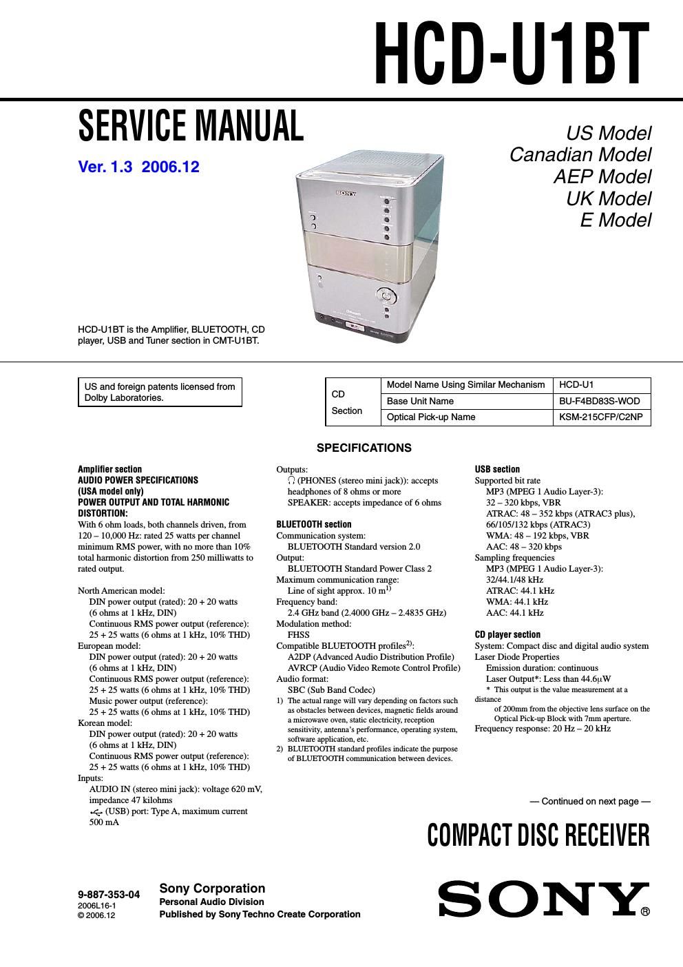
Sony hcd u1bt service manual

This is the 106 pages manual for sony hcd u1bt service manual.
Read or download the pdf for free. If you want to contribute, please mail your pdfs to info@audioservicemanuals.com.

Page: 1 / 106
left right
sony hcd u1bt service manual

Extracted text from sony hcd u1bt service manual (Ocr-read)


Page 1

HCD-U1BT

SERVICE MANUAL

Ver. 1.3 2006.12

HCD-U1BT is the Amplifier, BLUETOOTH, CD
player, USB and Tuner section in CMT-U1BT.

US Model
Canadian Model
AEP Model

UK Model

E Model

US and foreign patents licensed from
Dolby Laboratories.

Amplifier seolion

AUDIO POWER SPECIFICATIONS

(USA model only)

POWER OUTPUT AND TOTAL HARMONIC
DISTORTION:

With 6 ohm loads, both channels driven, from
120 - 10,000 Hz: rated 25 watts per channel
minimum RMS power, with no more than 10%
total harmonic distortion from 250 milliwatts to
rated output.

North American model:

DIN power output (rated): 20 + 20 watts

(6 ohms at 1 kHz, DIN)

Continuous RMS power output (reference):

25 + 25 watts (6 ohms at 1 kHz, 10% THD)
European model:

DIN power output (rated): 20 + 20 watts

(6 ohms at I kHz, DIN)

Continuous RMS power output (reference):

25 + 25 watts (6 ohms at 1 kHz, 10% THD)

Music power output (reference):

25 + 25 watts (6 ohms at 1 kHz, 10% THD)
Korean model:

DIN power output (rated): 20 + 20 watts

(6 ohms at 1 kHz, DIN)

Continuous RMS power output (reference):

25 + 25 watts (6 ohms at 1 kHz, 10% THD)
Inputs:

AUDIO IN (stereo mini jack): voltage 620 mV,

impedance 47 kilohms

4. (USB) port: Type A, maximum current

500 mA

Sony Corporation

9-887-353-04 . . . .
Personal Audio DIVISIon

2006L16-1
© 2006.12

Published by Sony Techno Create Corporation

Model Name Using Similar Mechanism

HCD-U1

CD
Base Unit Name

BU-F4BD83S-WOD

Section

Optical Pick-up Name

KSM-21SCFP/CZN P

SPECIFICATIONS

Outputs:
0 (PHONES (stereo mini jack)): accepts
headphones of 8 ohms or more
SPEAKER: accepts impedance of 6 ohms

BLUETOOTH section
Communication system:

BLUETOOTH Standard version 2.0
Output:

BLUETOOTH Standard Power Class 2
Maximum communication range:

Line of sight approx. 10 m
Frequency band:

2.4 GHz band (2.4000 GHz - 2.4835 GHz)
Modulation method:

FHSS
Compatible BLUETOOTH profilesz):

A2DP (Advanced Audio Distribution Profile)

AVRCP (Audio Video Remote Control Profile)
Audio format:
SBC (Sub Band Codec)
The actual range will vary depending on factors such
as obstacles between devices, magnetic fields around
a microwave oven, static electricity, reception
sensitivtty, antenna's performance, operating system.
software application, etc.
BLUETOOTH standard profiles Indicate the purpose
of BLUETOOTH communication between devices.

1

2

USB seolion

Supported bit rate
MP3 (MPEG 1 Audio Layer-3):
32 - 320 kbps, VBR
ATRAC: 48 - 352 kbps (ATRAC3 plus),
66/105/132 kbps (ATRAC3)
WMA: 48 - 192 kbps, VBR
AAC: 48 - 320 kbps

Sampling frequencies
MP3 (MPEG 1 Audio Layer-3):
32/44.l/48 kHz
ATRAC: 44.1 kHz
WMA: 44.1 kHz
AAC: 44.1 kHz

CD player section
System: Compact disc and digital audio system
Laser Diode Properties
Emission duration: continuous
Laser Output*: Less than 44.6ptW
* This output Is the value measurement at a
distance
of 200mm from the objective Iens surface on the
Optical Pickrup Block with 7mm aperture.
Frequency response: 20 Hz - 20 kHz

- Continued on next page -

COMPACT DISC RECEIVER

SONY®

Page 2

HCD-U1BT
Ver. 1.3

Tuner seclinn
FM stereo, FMJAM superheterodyne tuner

FM tuner section:
Tuning range
Pan-American models:
87.5 -108.0 MHz (100 kHz step)
Other models:
87.5 - 108.0 MHz (50 kHz step)
Antenna: FM lead antenna
Antenna terminals: 75 ohms unbalanced
Intermediate frequency: 10.7 MHz
AM tuner section:
Tuning range
Pan-American models:
530 - 1,710 kHz (with the tuning interval
set at 10 kHz)
531 - 1,710 kHz (with the tuning interval
set at 9 kHz)
European model:
531 - 1,602 kHz (with the tuning interval
set at 9 kHz)
Korean model:
530 - 1,710 kHz (with the tuning interval
set at 10 kHz)
531 - 1,602 kHz (with the tuning interval
set at 9 kHz)
Antenna: AM loop antenna, external antenna
terminal
Intermediate frequency: 450 kHz

Ge n e ral
Power requirements
North American model:

120 V AC, 60 Hz
European model:

220 - 240 V AC, 50/60 Hz
Korean model:

220 - 240 V AC, 60 Hz
Power consumption: 35 watts
Dimensions (w/h/d) (excl. speakers):
Approx. 160 x 241 x 218 mm
Mass (excl. speakers) 32 kg

Design and specifications are subject to change
without notice.

SAFETY CHECK-OUT

After correcting the original service problem, perform the following
safety check before releasing the set to the customer:

Check the antenna terminals, metal trim, metallized knobs, screws,
and all other exposed metal pans for AC leakage.

Check leakage as described below.

LEAKAGE TEST

The AC leakage from any exposed metal part to earth ground and
from all exposed metal parts to any exposed metal part having a
return to chassis, must not exceed 0.5 mA (500 microamperes)
Leakage current can be measured by any one of three methods

1. A commercial leakage tester, such as the Simpson 229 or RCA
WT-540A. Follow the manufacturers instructions to use these
instruments.

2 A battery-operated AC milliammeterr The Data Precision 245
digital multimeter is suitable for this job.

3. Measuring the voltage drop across a resistor by means of a
VOM or battery-operated AC voltmeter. The limit indication
is 0175 V, so analog meters must have an accurate low-voltage
scale The Simpson 250 and Sanwa SH-63Trd are examples
of a passive VOM that is suitable. Nearly all battery operated
digital multimeters that have a 2 VAC range are suitable. (See

Fig A)
To Exposed Metal
Pans on Set
AC
0. 15 HF g 1.5 k!) / voltmetel
(0.75 V)

_7_ Earth Ground
Fig. A. Using an AC voltmeter to check AC leakage.

SAFETY-RELATED COMPONENT WARNINGII

COMPONENTS IDENTIFIED BY MARK A OR DO'I'I'ED LINE
WITH MARK A ON THE SCHEMATIC DIAGRAMS AND IN
THE PARTS LIST ARE CRITICAL TO SAFE OPERATION.
REPLACE THESE COMPONENTS WITH SONY PARTS WHOSE
PART NUMBERS APPEAR AS SHOWN IN THIS MANUAL OR
IN SUPPLEMENTS PUBLISHED BY SONY.

ATTENTION AUCOMPOSANT AVANT RAPPORT
A LA SECURITE!

LES COMPOSANTS IDENTIFIES PAR UNE MARQUE ASUR
LES DIAGRAMMES SCHEMATIQUES ET LA LISTE DES
PIECES SONT CRITIQUES POUR LA SECURITE DE
FONCTIONNEMENT. NE REMPLACER CES com- POSANTS
QUE PAR DES PIECES SONY DONT LES NUMEROS SONT
DONNES DANS CE MANUEL 0U DANS LES SUPPLEMENTS
PUBLIES PAR SONY.