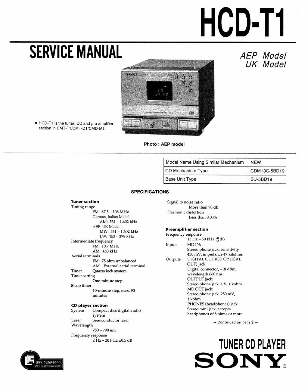
Sony hcd t1 service manual

This is the 27 pages manual for sony hcd t1 service manual.
Read or download the pdf for free. If you want to contribute, please mail your pdfs to info@audioservicemanuals.com.

Page: 1 / 27
left right
sony hcd t1 service manual

Extracted text from sony hcd t1 service manual (Ocr-read)


Page 2

Power consumption
25 W

Dimensions
Approx 142 x125 x 252 mm
(W/h/d) (55/5 x 5 x 10 inches)
incl. projecting parts and
controls

Mass Approx. 3 kg (6 lb 10 oz)

General

Power requirements
220 - 230 V AC, 50/60 Hz

Supplied accessories
AM loop aerial (1)
Remote (1)
Sony SUMa3 (NS) batteries (2)
FM lead aerial (1)
Speaker cable (1)
Audio cord (1)

Design and specifications are subject to
change without notice,

Laser component in this product is capable of emitting radiation
exceeding the limit for Class 1.

This appliance is classified as a
CLASS 1 LASER product.
LUOKAN LASERLAITE The CLASS 1 LASER PRODUCT
KLASS LASEFIAPPAFIAT MARKING is located on the rear
exteriori

CLASS 1 LASER PRODUCT

This caution

CAUTION 'memg,,,tg:5:§w*tg,°~ W W label is located

AUVAFISEL ~ gimggzgssgsrwmam Venn ABNING mmnm "15de the unit,
UMDGA uus Erma: ma 5?»:an

-. , AVAYVAESSA a sumumus mamas.
VARO 01.21 ALYnINA MSHSAEILVLLE

' LASERSYRMJNG MAR DENNA DEL KR OGPNAD
VARNNG OCH SPARREN b! URXO PluD

WW

CAUTION

Use of controls or adjustments or performance
of procedures other than those specified herein
may result in hazardous radiation exposure.

SAFETY- RELATED COMPONENT WARNING]!

COMPONENTS IDENTIFIED BY MARK A OR DOTTED
LINE WITH MARK A ON THE SCHEMATIC DIAGRAMS
AND IN THE PARTS LIST ARE CRITICAL TO SAFE
OPERATION, REPLACE THESE COMPONENTS WITH
SONY PARTS WHOSE PART NUMBERS APPEAR AS
SHOWN IN THIS MANUAL OR IN SUPPLEMENTS PUB-
LISHED BY SONY.

TABLE OF CONTENTS

Section Title Page
1. SERVICING NOTES .............................................. 2
2, GENERAL ............................................................. 3
3_ DISASSEMBLY ..................................................... 4
4' Bfiifiéfibivéfigb'ééflfl $199599??? ................ 5
5. ELECTRICAL ADJUSTMENTS' ~6
6. EXPLANATION OF IC TERMINALS ......................... 9
7. DIAGRAMS

7-1. Printed Wiring Boards - Main Section - ~
7-2, Schematic Diagram ~ Main Section - -
7-3. Printed Wiring Boards - BD Section -
7-4. Schematic Diagram - BD Section -

8. EXPLODED VIEWS
8-1. Front Panel Section -
8'2. Chassis Section
8»3r Mechanism Section»
8-4. Mechanism Section-2

9. ELECTRICAL PARTS LIST ~~~~~~~~~~~~~~~~~~~~~~~~~~~~~~~~~~ 27


SECTION 1
SERVICING NOTES

NOTES ON HANDLING THE OPTICAL PICK-UP BLOCK
OR BASE UNIT

The laser diode in the optical pick-up block may suffer electrostatic
breakdown because of the potential difference generated by the
charged electrostatic load, etc on clothing and the human body
During repair, pay attention to electrostatic breakdown and also use
the procedure in the printed matter which is included in the repair
parts.

The flexible board is easily damaged and should be handled with
care

NOTES ON LASER DIODE EMISSION CHECK

The laser beam on this model is concentrated so as to be focused on
the disc reflective surface by the objective lens in the optical
pick-up blockl Therefore, when checking the laser diode emission,
observe more than 25cm away form the objective lens,

CHUCK PLATE JIG ON REPAIRING

On repairing CD section, playing a disc without the CD lid, use
Chuck Plate J ig,
0 Code number of Chuck Plate Jig : X»4918-255-1