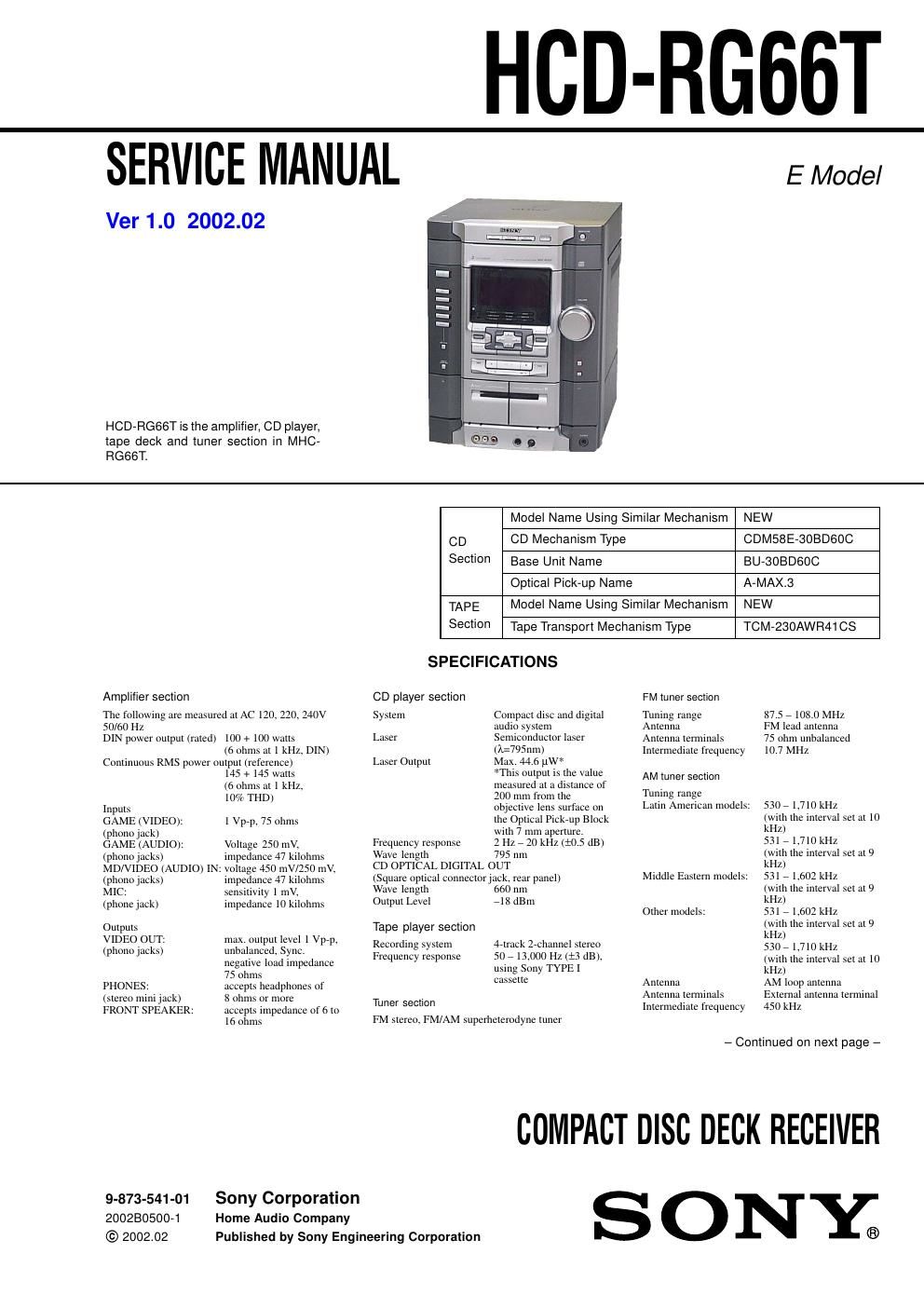
Sony hcd rg 66 t service manual

This is the 72 pages manual for sony hcd rg 66 t service manual.
Read or download the pdf for free. If you want to contribute, please mail your pdfs to info@audioservicemanuals.com.

Page: 1 / 72
left right
sony hcd rg 66 t service manual

Extracted text from sony hcd rg 66 t service manual (Ocr-read)


Page 2

HCD-RG66T 3 TABLE OF CONTENTS 1. SERVICING NOTES ................................................ 4 2. GENERAL Location of Controls ....................................................... 5 Setting the Clock ............................................................. 6 3. DISASSEMBLY 3-1. Disassembly Flow ........................................................... 7 3-2. Top Case .......................................................................... 8 3-3. Loading Panel .................................................................. 8 3-4. CD Mechanism Deck (CDM58E-30BD60C) ................. 9 3-5. Front Panel Section ......................................................... 9 3-6. Back Panel Section .......................................................... 10 3-7. MAIN Board ................................................................... 10 3-8. Base Unit (BU-30BD60C) .............................................. 11 3-9. DRIVER Board, MOTOR Board and SENSOR (CD) Board .............................................. 11 3-10. Tape Mechanism Deck (TCM-230AWR41CS) .............. 12 3-11. Belt .................................................................................. 12 3-12. SW Board, HEAD (A) Board and HEAD (B) Board ...................................................... 13 4. TEST MODE .............................................................. 14 5. MECHANICAL ADJUSTMENTS ....................... 18 6. ELECTRICAL ADJUSTMENTS Deck section .................................................................... 18 CD Section ...................................................................... 21 7. DIAGRAMS 7-1. Block Diagram -“ CD SERVO Section -“ ....................... 23 7-2. Block Diagram -“ TUNER/TAPE DECK Section -“ ...... 24 7-3. Block Diagram -“ MAIN Section -“ ................................ 25 7-4. Block Diagram -“ DISPLAY/KEY CONTROL/ POWER SUPPLY Section -“ ........................................... 26 7-5. Note for Printed Wiring Boards and Schematic Diagrams ....................................................... 27 7-6. Printed Wiring Board -“ BD Board -“ ............................. 28 7-7. Schematic Diagram -“ BD Board -“ ................................ 29 7-8. Printed Wiring Boards -“ DRIVER/MOTOR/SENSOR (CD) Boards -“ .............. 30 7-9. Schematic Diagram -“ DRIVER/MOTOR/SENSOR (CD) Boards -“ .............. 30 7-10. Printed Wiring Boards -“ SW/HEAD (A)/HEAD (B) Boards -“ .......................... 31 7-11. Schematic Diagram -“ SW Board -“ ................................ 32 7-12. Printed Wiring Boards -“ MAIN Board -“ ....................... 33 7-13. Schematic Diagram -“ MAIN Board (1/4) -“ .................. 34 7-14. Schematic Diagram -“ MAIN Board (2/4) -“ .................. 35 7-15. Schematic Diagram -“ MAIN (3/4)/HEAD (A)/HEAD (B) Boards -“ ............. 36 7-16. Schematic Diagram -“ MAIN Board (4/4) -“ .................. 37 7-17. Printed Wiring Board -“ GAME IN Board -“ .................. 38 7-18. Schematic Diagram -“ GAME IN Board -“ ..................... 39 7-19. Printed Wiring Boards -“ POWER/SENSOR Boards -“ ........................................ 40 7-20. Schematic Diagram -“ POWER/SENSOR Boards -“ ........................................ 41 7-21. Printed Wiring Boards -“ PANEL/CD OPEN/CD SWITCH Boards -“ ................ 42 7-22. Schematic Diagram -“ PANEL/CD OPEN/CD SWITCH Boards -“ ................ 437-23. Printed Wiring Boards -“ PAD SWITCH/VOL Boards -“ ..................................... 44 7-24. Schematic Diagram -“ PAD SWITCH/VOL Boards -“ ..................................... 45 7-25. Printed Wiring Boards -“ MAIN TRANS/SUB-TRANS Boards -“ ...................... 46 7-26. Schematic Diagram -“ MAIN TRANS/SUB-TRANS Boards -“ ...................... 47 7-27. IC Pin Function Description ........................................... 49 8. EXPLODED VIEWS 8-1. Panel Section ................................................................... 53 8-2. Front Panel Section ......................................................... 54 8-3. Chassis Section ............................................................... 55 8-4. CD Mechanism Deck Section (CDM58E-30BD60C) ..................................................... 56 8-5. Base Unit Section (BU-30BD60C) ................................. 57 8-6. Tape Mechanism Deck Section (TCM-230AWR41CS) .................................................... 58 9. ELECTRICAL PARTS LIST ............................... 59