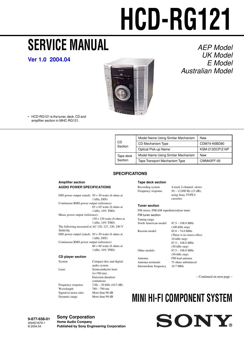
Sony hcd rg 121 mhc rg 121 manual servico mini hi fi
This is the 66 pages manual for sony hcd rg 121 mhc rg 121 manual servico mini hi fi. Read or download the pdf for free.
If you want to contribute, please mail your pdfs to info@audioservicemanuals.com.
Page: 1 / 66
Extracted text from sony hcd rg 121 mhc rg 121 manual servico mini hi fi (Ocr-read)
Page 1
2
HCD-RG121
SAFETY-RELATED COMPONENT WARNING!!
COMPONENTS IDENTIFIED BY MARK 0 OR DOTTED LINE WITH
MARK 0 ON THE SCHEMATIC DIAGRAMS AND IN THE PARTS
LIST ARE CRITICAL TO SAFE OPERATION. REPLACE THESE
COMPONENTS WITH SONY PARTS WHOSE PART NUMBERS
APPEAR AS SHOWN IN THIS MANUAL OR IN SUPPLEMENTS
PUBLISHED BY SONY.
General
Po wer requirementsEuropean and Russian models:
110 watts0.25 watts (at the Power
Savi ng Mode)
Other models: 110 watts
Dimensions (w/h/d) incl. projecting parts and contro ls
A mplifier/Tuner/Tape/CD section: Approx. 280 Γ 327 Γ
425 mm
Ma ss European and Russian models:
Approx. 8.5 kg
Other models:
Design and specifications are subject to change without notice. Approx. 8.5 kg
AM tuner
section
Tuning rangePan-A me rica n models: 530 - 1,710 kHz
(with the tuning interval
set at 10 kHz)
531 - 1,710 kHz
(with th e tuning interval
set at 9 kHz)
European, Russian and Saudi Arabian models: 531 - 1,602 kHz (with th e tuning interval set at
9kHz)
Other models:530 - 1,710 kHz
(with th e tuning interval
set at 10 kHz)
531 - 1,602 kHz
(with th e tuning interval
set at 9 kHz)
Antenna AM loop antennaAntenna terminals External antenna termina l
I ntermediate frequency 450 kHz
The release method of a CD disc tray LOCK function
There is a disc lock function for the disc theft prevention for a
demonstration at a shop front in this machine.
Procedue:
1. Press the ?/1 button to turn the set on.
2. Press two buttons of x and
Z
(EJECT) simultaneously for
fi ve seconds.
3. The message LOCKED is displayed and the tray is locked. (Even if exiting from this mode, the tray is still locked.)
4. Press two buttons of x and
Z
(EJECT) simultaneously for
fi ve seconds again.
5. The message UNLOCKED is displayed and the tray is
unlocked.
6. To exit from this mode, press the ?/1 button to turn the set
off.
This appliance is classified as a CLASS 1 LASER product. The
CLASS 1 LASER PRODUCT MARKING is located on the rear
e xterior.
Notes on chip component replacement
-N ever reuse a disconnected chip component.
- Notice that the minus side of a tantalum capacitor may be
damaged by heat.
Flexible Circuit Board Repairing
-K eep the temperature of soldering iron around 270ΛC
during repairing.
- Do not touch the soldering iron on the same conductor of the
circuit board (within 3 times).
- Be careful not to apply force on the conductor when soldering
or unsoldering.
NOTES ON HANDLING THE OPTICAL PICK-UP
BLOCK OR BASE UNIT
The laser diode in the optical pick-up block may suffer electrostatic
break-down because of the potential difference generated by the
charged electrostatic load, etc. on clothing and the human body.
During repair, pay attention to electrostatic break-down and also
use the procedure in the printed matter which is included in the
repair parts.
The flexible board is easily damaged and should be handled with
care.
NOTES ON LASER DIODE EMISSION CHECK
The laser beam on this model is concentrated so as to be focused on
the disc reflective surface by the objective lens in the optical pick-
up block. Therefore, when checking the laser diode emission,
observe from more than 30 cm away from the objective lens.
CAUTION
Use of controls or adjustments or performance of procedures
other than those specified herein may result in hazardous radiation
e xposure.
Laser component in this product is capable
of emitting radiation exceeding the limit for
Class 1.
Page 2
3
HCD-RG121
TABLE OF CONTENTS
1. SERVICE POSITION
............................................... 4
2. GENERAL ................................................................... 6
3. DISASSEMBLY
3-1. Cover (Top) ........................................................... 9
3-2. CD Door ................................................................ 9
3-3. Front Panel Section ............................................... 10
3-4. CD Mechanism Deck (CDM74-K6BD80) ............ 10
3-5. Tape Mechanism Deck, GAME JACK Board ....... 11
3-6. PANEL Board ........................................................ 11
3-7. Back Panel Section, SUB-TRANS Board ............. 12
3-8. Power Transformer ................................................ 12
3-9. MAIN Board ......................................................... 13
3-10. AMP Board ........................................................... 13
3-11. BD80A Board ........................................................ 14
3-12. CONNECT Board ................................................. 14
3-13. DRIVER Board, SW Board .................................. 15
3-14. Optical PICK-UP (KSM-213DCP/Z-NP) ............. 15
3-15. SENSOR Board ..................................................... 16
3-16. MOTOR (TB) Board ............................................. 16
3-17. MOTOR (LD) Board ............................................. 17
4. TEST MODE ............................................................... 18
5. DIAGRAMS
5-1. Block Diagram - PANEL Section - ...................... 22
5-2. Block Diagrams - MAIN Section - ...................... 23
5-3. Block Diagrams - BD/DRIVER Section - ........... 24
5-4. Printed Wiring Board - BD80A Section - ............ 25
5-5. Schematic Diagram - BD80A Section - ............... 26
5-6. Printed Wiring Board - CD MECHANISM Section - ............................. 27
5-7. Schematic Diagram - CD MECHANISM Section - ............................. 28
5-8. Printed Wiring Board - MAIN Section - .............. 29
5-9. Schematic Diagram - MAIN Section (1/2) - ........ 30
5-10. Schematic Diagram - MAIN Section (2/2) - ........ 31
5-11. Printed Wiring Board - PANEL COMB Section - ................................... 32
5-12. Schematic Diagram - PANEL COMB Section - ................................... 33
5-13. Printed Wiring Board - PANEL Section - ............ 34
5-14. Schematic - PANEL Section (1/2) - ..................... 35
5-15. Schematic - PANEL Section (2/2) - ..................... 36
5-16. Printed Wiring Board - TRANS Section - ........... 37
5-17. Printed Wiring Board - AMP Section - ................ 38
5-18. Schematic Diagram - AMP POWER Section - .... 39
5-19. IC Pin Function Description .................................. 42
6. EXPLODED VIEWS
6-1. MAIN Section ....................................................... 48
6-2. Front Panel Section ............................................... 49
6-3. MAIN Board Section ............................................ 50
6-4. CD Mechanism Deck Section-1 (CDM74-K6BD80) ............................................... 51
6-5. CD Mechanism Deck Section-2 (CDM74-K6BD80) ............................................... 52
7. ELECTRICAL PARTS LIST .................................. 53
Unleaded solder
Boards requiring use of unleaded solder are printed with the lead-
free mark (LF) indicating the solder contains no lead.
(Caution: Some printed circuit boards may not come printed with
the lead free mark due to their particular size.)
: LEAD FREE MARK
Unleaded solder has the following characteristics.
- Unleaded solder melts at a temperature about 40Β°C higher than
ordinary solder.
Ordinary soldering irons can be used but the iron tip has to be
applied to the solder joint for a slightly longer time.
Soldering irons using a temperature regulator should be set to
about 350Β°C.
Caution: The printed pattern (copper foil) may peel away if the
heated tip is applied for too long, so be careful!
- Strong viscosity
Unleaded solder is more viscous (sticky, less prone to flow) than
ordinary solder so use caution not to let solder bridges occur
such as on IC pins, etc.
- Usable with ordinary solder
It is best to use only unleaded solder but unleaded solder may
also be added to ordinary solder.