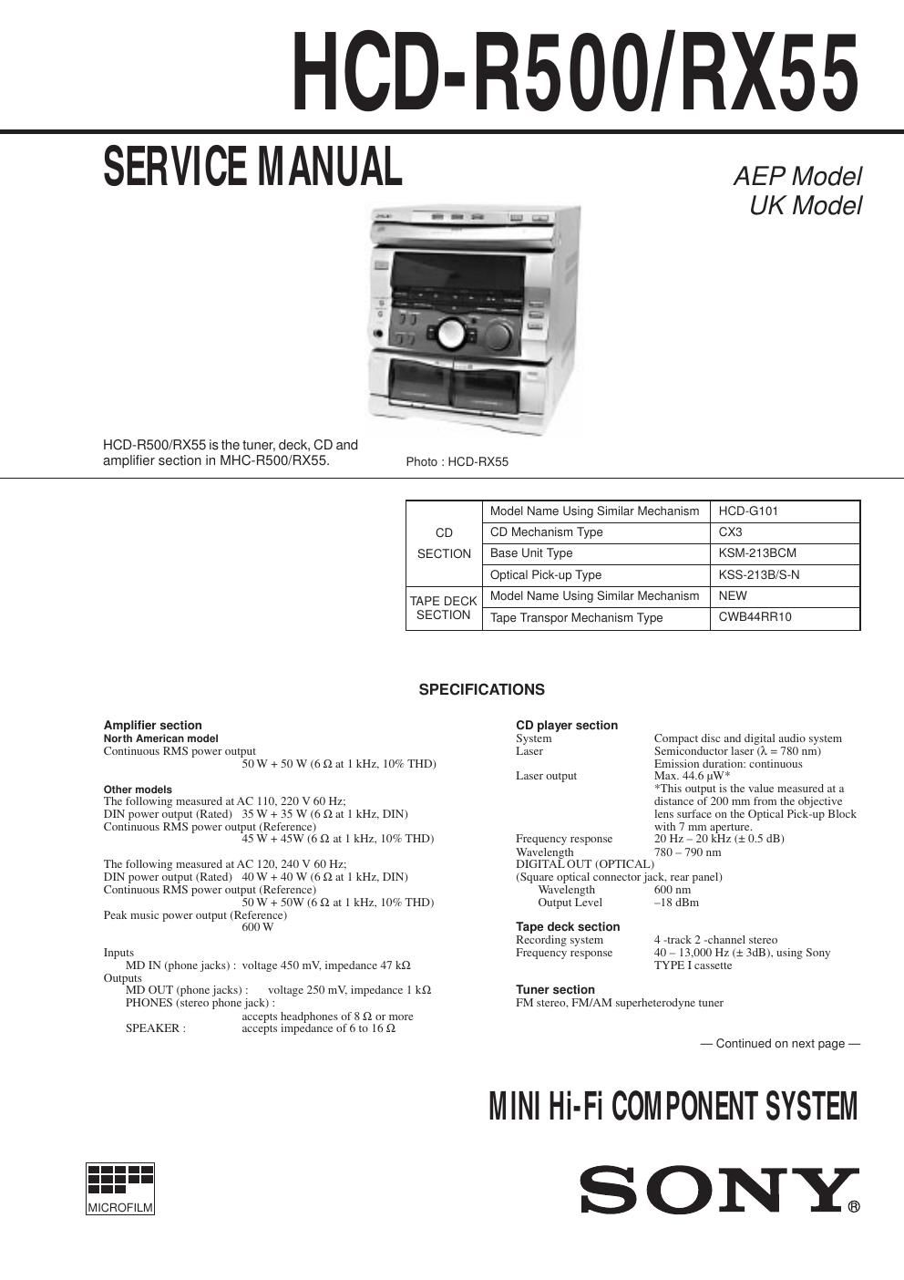
Sony hcd r 500 service manual

This is the 42 pages manual for sony hcd r 500 service manual.
Read or download the pdf for free. If you want to contribute, please mail your pdfs to info@audioservicemanuals.com.

Page: 1 / 42
left right
sony hcd r 500 service manual

Extracted text from sony hcd r 500 service manual (Ocr-read)


Page 2

TABLE OF CONTENTS 1. GENERAL .......................................................................... 4 2. DISASSEMBLY 2-1. Upper Cover and CD Door ................................................. 5 2-2. Front Panel ......................................................................... 5 2-3. Main Board ......................................................................... 6 2-4. Amp Board ......................................................................... 6 2-5. CD Tray .............................................................................. 7 2-6. CD Decoder Board ............................................................. 7 2-7. Base Unit ............................................................................ 8 2-8. Cassette Door ..................................................................... 8 3. MECHANICAL ADJUSTMENTS ............................... 9 4. ELECTRICAL ADJUSTMENTS ................................. 9 5. DIAGRAMS 5-1. Circuit Boards Location ................................................... 14 5-2. Block Diagrams ¥ Deck Section ................................................................... 15 ¥ CD Section ...................................................................... 17 5-3. IC Block Diagrams ........................................................... 19 5-4. Printed Wiring Board ÑCD Section Ñ ........................... 24 5-5. Schematic Diagram Ñ CD Section Ñ ............................. 29 5-6. Schematic Diagram ÑPanel Section Ñ .......................... 33 5-7. Printed Wiring Board ÑPanel Section Ñ ........................ 37 5-8. Printed Wiring Board Ñ Deck Section Ñ ....................... 42 5-9. Schematic Diagram ÑDeck Section Ñ ........................... 47 5-10. Schematic Diagram ÑMain Section Ñ ........................... 51 5-11. Printed Wiring Board ÑMain Section Ñ ........................ 55 5-12. Printed Wiring Board Ñ Amp Section Ñ ........................ 60 5-13. IC Pin Function ................................................................ 65 6. EXPLODED VIEWS 6-1. Cabinet Section ................................................................. 67 6-2. Front Panel Section .......................................................... 68 6-3. Cassette Mechanism Deck Section ................................... 69 6-4. CD Mechanism Deck Section 1 ....................................... 70 6-5. CD Mechanism Deck Section 2 ....................................... 71 6-6. Base Unit Section (KSM-213BCM) ................................. 72 7. ELECTRICAL PARTS LIST ........................................ 73 Ñ 3 Ñ