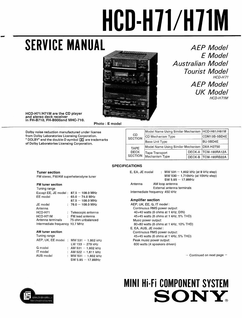
Sony hcd h 71 service manual

This is the 73 pages manual for sony hcd h 71 service manual.
Read or download the pdf for free. If you want to contribute, please mail your pdfs to info@audioservicemanuals.com.

Page: 1 / 73
left right
sony hcd h 71 service manual

Extracted text from sony hcd h 71 service manual (Ocr-read)


Page 2

Inputs
E, EA. AUS, JE model
MIX MIC (minijack):
Sensitivity 1 mV,
impedance 600 ohms
VIDEO/AUX (phono jack):
sensitivity 250 mV,
impedance 47 kilohms
AEP, UK, EE. G, IT model :
PHONO (phono jack):
sensitivity 5 mV,
impedance 47 kilohms
Outputs
HEADPHONES (stereo miniiack);
accept headphones of 8 ohms
or more.
SPEAKERS: accept impedance ole to
16 ohms
SURROUND SPEAKERS (only for
E. EA. AUS, JE model) :
accept impedance ol 8 to 16 ohms.

Compact disc player section
System Compact disc digital audio system
Laser Semiconductor laser

Wavelength 780 - 790 nm

Cassette deck section
Recording system

4-track 2»channel stereo
Frequency response

(DOLBY NR OFF)

60 -13,000 Hz (13 dB),

using TYPE I

cassette (Sony HF~S)

60 -14,000 Hz (13 dB),

using TYPE lI

cassette (Sony UX-S)
Wow and llutter

0.1% WFIMS i013°/o (DIN)

General
, 1 Power Power
Destination requirements consumption
AEP, EE. G. 220 - 230 V
IT model Ac, 50/60 Hz I W
UK model 240 V AC. 250 W
AUS model 50' 170 w
EEAEJE 110*120/V
mo 9 220 - 240
AC. ad'ustable. 17° W
50/80 2
Dimensions

Approx 225 x 285 x 265 mm (w/h/d)

(8 7/5 x 11 l: x 10 /2 inches)

incl. projecting parts and controls
Mass Approx. 6.6 kg (14 lb 8 02)

NOTE
EE : East European EA : Saudi Arabia
G : German AUS: Australian
IT : Italian IE : Tourist

TABLE OF CONTENTS

Section 11212 11152
1. SERVICING NOTE ..................... 3
2. GENERAL

Parts Identification ------------------------ 4

Clock Setting ~~~~~~~~~~~~~~~~~~~~~~~~~~~~ 5
3. DAIAGRAMS
3-1. Semiconductor Lead Layouts - - . - 6
3-2. Circuit Boards Docation ~~~~~~~~ - - 8
33. IC Block Diagram (MAIN SECTION) ~~~~~~~ 9
3-4. Printed Wiring Boards (MAIN SECTION)

- AEP, UK. EE, G, IT MODEL - ---------- 12
3-5. Schematic Diagram (MAIN SECTION)

- AEP, UK, EE, G, IT MODEL - ---------- 15
3-6. Printed Wiring Boards (MAIN SECTION)

- MAIN BOARD:E,EA,AUS,JE MODEL - - 19
3-7, Schematic Diagram (MAIN SECTION)

- MAIN BOARD:E,EA,AUS,JE MODEL - . 23
3-81 Printed Wiring Boards (DECK SECTION) ~ - - - 27
3-91 Schematic Diagram (DECK SECTION) ----- 31
3-10. Printed Wiring Boards

(DISPLAY SECTION) ------------------- 36
3-11. Schematic Diagram (DISPLAY SECTION) . - 39
3-12. IC Block Diagram (DISPLAY SECTION) - ~ ~ 42
3-131 IC Block Diagram (CD SECTION) --------- 43
3-14, Printed Wiring Boards (CD SECTION) ~~~~~~ 39
34's. Schematic Diagram (CD SECTION) ~~~~~~~~~ 47
4. EXPLODED VIEWS
4-1. Case. Power Section ~~~~~~~~~~~~~~~~~~~~ 51
4-2. Front Panel Section ~~~~~~~~~~~~~~~~~~~~~~ 52
4-3. Mechanism Deck Chassis Section ---------- 53
4-4. Tape Mechanism Deck Section] ---------- 54
4-5, Tape Mechanism Deck Section-2 ------------ 55
4-6 CD Mechanism Section-1 4 ~~~~~~~~~~~ 56
4-71 CD Mechanism Section-2 ------------------ 57
5. ELECTRICAL PARTS LIST ------------ 58

SUPPLEMENT-1

SAFETY-RELATED COMPONENT WARNING

COMPONENTS IDENTIFIED BY MARK A OR DOTTED
LINE WITH MARK & ON THE SCHEMATIC DIAGRAMS
AND IN THE PARTS LIST ARE CRITICAL TO SAFE
OPERATION. REPLACE THESE COMPONENTS WITH
SONY PARTS WHOSE PART NUMBERS APPEAR AS
SHOWN IN THIS MANUAL OR IN SUPPLEMENTS PUB~
LISHED BY SONV.