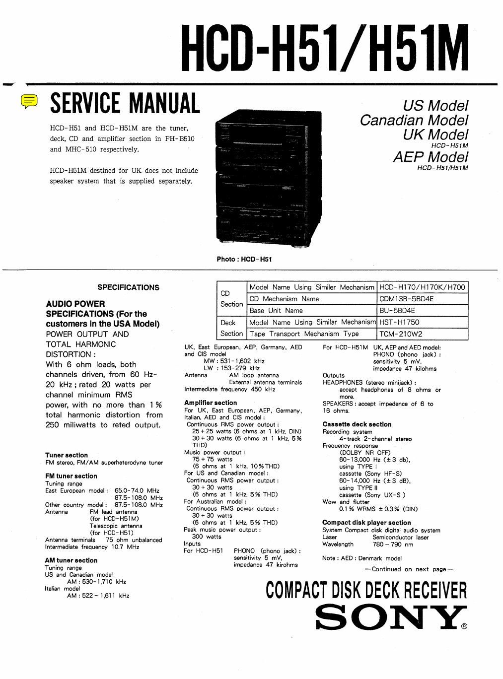
Sony hcd h 51m

This is the 5 pages manual for sony hcd h 51m.
Read or download the pdf for free. If you want to contribute, please mail your pdfs to info@audioservicemanuals.com.

Page: 1 / 5
left right
sony hcd h 51m

Extracted text from sony hcd h 51m (Ocr-read)


Page 1

HCD-H51/H51M

'- SERVICE MANUAL

US Model
Canadian Model
UK Model

HCD- H51M

AEP Model

HCD- H51/H51M

HCD-HSI and HCD-HSIM are the tuner,
deck, CD and amplifier section in FHBSIO
and MHC-Slo respectively.

HCD-HSIM destined for UK does not include
speaker system that is supplied separately.

Photo : HCD- H51

SPECIFICATIONS CD Model Name Using Similer Mechanism HCD-Hl70/H17OK/H700
h ,
AUDIO POWER Section CD Meclanism Name CDMISB 53045
SPECIFICATIONS (For the Base Uh" Name BU'58D4E
customers in the USA Model) Deck Model Name Using Similar Mechanism HST-H1750
POWER OUTPUT AND Section Tape Transport Mechanism Type TCM-ZlOWZ

TOTAL HARMONlC
DlSTORTlON :

With 6 ohm loads, both
channels driven, from 60 Hz-
20 kszrated 20 watts per
channel minimum RMS

power, with no more than 1%
total harmonic distortion from
250 miliwatts to reted output.

Tuner section
FM stereo, FM/AM superheterodyne tuner

FM tuner section
Tuning range
East European model: 65.0-74.0 MHz
BIS-108.0 MHz
Other country model: BIS-108.0 MHz
Antenna FM lead antenna
(for HCD-H51M)
Telescopic antenna
(for HCD-HSI)
Antenna terminals 75 ohm unbalanced
Intermediate frequency 10.7 MHz

AM tuner sectlon
Tuning range
US and Canadian model
AM : 5304.710 kHz
Italian model
AM : 522 - 1.611 kHz

UK. East European. AEP, Germany, AED
and CIS model
MW:531-1.602 kHz
LW : 153~279 kHz
Antenna AM loop antenna
External antenna terminals
Intermediate frequency 450 kHz

Amplifier section

For UK. East European. AEP. Germany.

ltalian. AED and ClS model:

Continuous RMS power output:
25+25 watts (6 ohms at 1 kHz. DIN)
30+30 watt: (6 ohms at 1 kHz. 5%
THD)

Music power output:

75 + 75 watts
(6 ohms at 1 kHz. 10%THD)

For US and Canadian model:

Continuous RMS power output:
30 + 30 watts
(6 ohms at 1 kHz. 5% THD)

For Australian model:

Continuous HMS power output:
80 + 30 watts
(6 ohms at 1 kHz. 5% THD)

Peak music power output:

300 watts
inputs

For HCD-H51 PHONO (phono jack):

sensitivity 5 mV.

impedance 47 kirohms

For HCD-H51M UK. AEPand AED model:
PHONO (phone jack) :
sensitivity 5 mV,
impedance 47 kilohms
Outputs
HEADPHONES (stereo miniiack) :
accept headphones of 8 ohms or
more.
SPEAKERS:accept impedance of 6 to
16 ohms.

Cassette deck section
Recording system
4-traok 2-channel stereo
Frequency response
(DOLBY NR OFF)
60-13000 Hz (13 db).
using TYPE 1
cassette (Sony HF-S)
60-14000 Hz (:3 dB).
using TYPE ll
cassette (Sony UX-S )
Wow and flutter
0:156 WRMS 10.3% (DIN)

Compact dlsk player section

System Compact disk digital audio system
Laser Semiconductor laser
Wavelength 780 - 790 nm

Note : AED : Denmark model
-Cr.>ntinued on next page--

COMPACT DISK DECK RECEIVER

ONE.

Page 2

HCD- H51/H51M

6~ 4. SCHEMATIC DIAGRAM - BD SECTION -- 0 See page 41 for IC Block Diagrams.
1 2 3 4 5 6 7 8 9 I 10 11 12 l 13 I 14 15 I 16 17 18 19 20 21 22 23 I 24 | 25 26 | 27 l

A
LOADI N G m,
B OAR D LOADING
-. MOTOR
B OPTICAL PICK-UP BLOCK (KSS-240A) A [30 BOARD]
_ .. _ -
C
11 11 II) I! {3
I & lg é g g i E E E 51 59 u 7 £6 £5 u 53 £2 51 w 59 st 37
_. DETECTOR E 5 " 9 "
RF AMP 3 é a _ E E
I
a s s 3 E
5 I: § 31 I
D ;: IN 3o
26
.. IN 27
._ 5.0
I R223 22k 0202 V55 1
LDBIN
51:24 22k *7 $755210? LOB out 24
0 Wave forms E R215 22x SYSTEM CONTROL 13
R226 22x
0 1- n
ND-D FUEUS con. :- F 21
J- etc-minor: GFSZII
TRAKKINGCOIL E i}
y »- -)
0.25115» B-Kss-zmA % on, 3 In I
_- - -_. - 2 3 ' l
ICZOI @ F 16 17 8 IS
VD, 0201 155355
P-fi -L ;
0.24usec 2 J . .
lCSOl ® _ ._. AUDIO BUS
G cNIoz |2p zsaczfils; BUFFER |
5VDD
l---- 3lusec
IC501 ®
H I II N Is
9 -T I: z I
z <
wow Iczus
- 5 5 5 : cxazssm
FECT sw § g g g g 5 5 DIGITAL
4W1 DE lTCH FILTER
9 W II II
IC202. |
m
6 3°
.,
-l-
I
l$MH1
3 62 5| All
IC203©
J 0102 m; a? 235? a: To
© \Vo'o'o'goo'oooggfl 1 PWM M07011 ,5. .1 "' " " § r MAIN BOARD
.0...Q.O..l.o.0m0. DRI VER of? G C N 70 4
IIIIIIIIIIOI. IZVo-n __ u m,
I'oI'IIIIIIIIIi ° ;
\.,o,o.o.0.o.o.0.o.o.~s. _L s : e
" 5 sens 2 5 N _ 21
IClOi @play (RFO) K - xnst ..
m g; 0 " ° 2.5
EA r 2 on : s I
Note on Schematic Dlngnm : .- XLAT "m f 2 .o "
" 2 m cxnzsoan 4-5 52 _., m s A 7 a a
. . A - I a mm on DIGITAL - 2,
UNI capacrtors are in uF unless otherwise notedt pF: upF :. 0013720 CLUK SIGNAL pfiocESSOR WCK I '2 ~0 2.5
sowv or less are not indlcated except for electrolytics and mm am 21 3 mam! EFM COMPARATOR 551" CLV SERVO FSSL =° - 33 5" lCSOZ
AD-J 3 - 1 2x a
mum. at a ""235 my '2 use FOCUS/TRACKING/SLED 19 g. N '- 55" I
_ .o 1.0 .-
OAII resistors are in Q and Z W or less unless otherwise L - "55 '3 FIE SERVO 0 SL- 2a
SIMWM : m" .5 G 5 2
0 E: fuslble resistor. _ 5 Icsm
: :1 man 6" 1- Q PCHHU
Note: Note: - 573 °~' _ _ g ' «I N N
The components Identi< Les oomposants identifies par 7 u 1 "" x 3 k m > 3 C30
fied by matk A or dot- une marque A son! critiques ' i 2 5 l 5 A 7 a 9 III E § 3 {13 E 3 I § < E 3 E
ted line with mark A pourla sécurité. D/A
amcritlcaliorsafety. Ne les remplaoer que par one I 5 7 a 9 W H 2 l 5 1 '7 u '5 1° 1' CONVERTER
Replace only with part piece portant le numéro spéci- M PE1 , AUDIO AMP
numbersppecifiedt fie. 1w -.0.8
. Ioi
61715.2
6 m :B + Line. I |
9 mm :3 ~ Line, R103 56! RH 120k
V . am In Rwoz
a ,aolustmentfiorre any.
i: p M102 FOCUS GAlN


eVoltage and waveforms are do with respect to ground under
no-signaE conditions.
no mark : CD STOP

0 Voltages are taken with a VOM (input impedance 10 M9).
Voltage variations may be noted due to normal production
tolemnces.

e Waveforms are taken with a oscilloscope.
Voltage variations may be noted due to normal production
tolerances. O - - - - - - - -

0 circled numbers refer to waveforms 16 _

9 Signal path,

W : CD

ADJ.

SP
mum
N

-21 - ~22- -23- -24-