Sony hcd h 51 m service manual

This is the 42 pages manual for sony hcd h 51 m service manual.
Read or download the pdf for free. If you want to contribute, please mail your pdfs to info@audioservicemanuals.com.

Page: 1 / 42
left right
sony hcd h 51 m service manual

Extracted text from sony hcd h 51 m service manual (Ocr-read)


Page 1

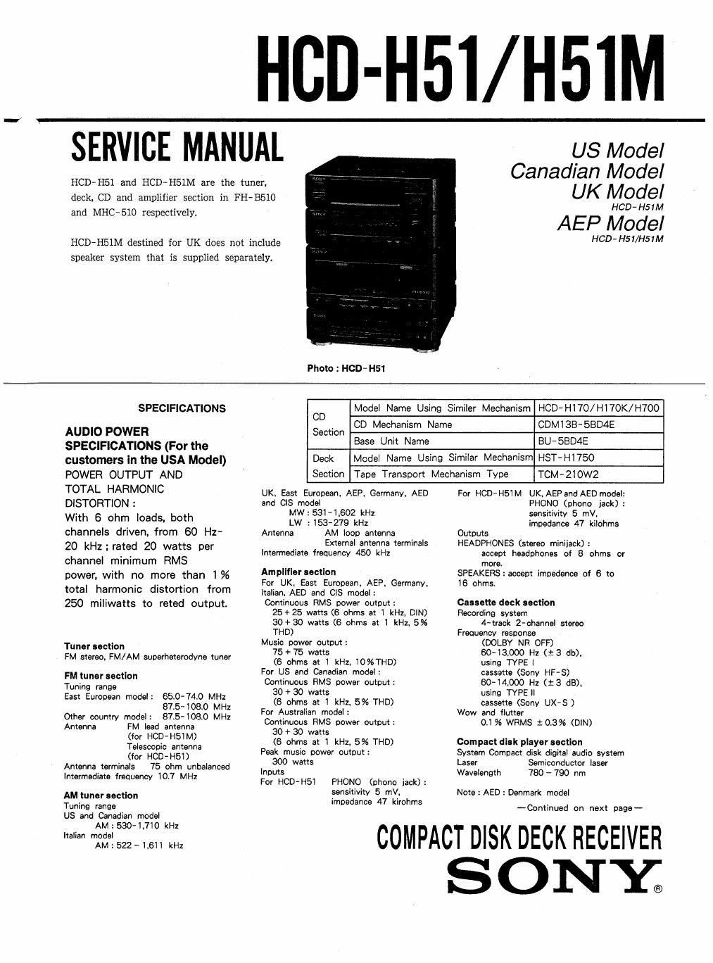
HBD-H51/H5IM

SERVICE MANUAL

HCD-HSl and HCD-H51M are the tuner.
deck, CD and amplifier section in FH-BSlO

and MEG-510 respectively.

HCD-HSlM destined for UK does not include
speaker system that is supplied separately.

Photo : HCD H51

US Model
Canadian Model
UK Model

HCD- H51M

AEP Model

HCD- H51/H51M

SPECIFICATIONS

AUDIO POWER
SPECIFICATIONS (For the
customers In the USA Model)
POWER OUTPUT AND

TOTAL HARMONIC
DISTORTION :

With 8 ohm loads. both
channels driven, from 60 Hz-
20 kszrated 20 watts per
channel minimum RMS

power. with no more than 1%
total harmonic distortion from
250 miliwatts to reted output.

Tuner section
FM stereo. FM/AM superheterodyne tuner

FM tuner section
Tunino range

East European model: 65.0-74.0 MHz
875-1080 MHz
Other country model: 875-1080 MHz

FM lead antenna

(for HCD-HSIM)
Telescopic antenna

(for HCD-HSI)

Antenna terminals 75 ohm unbalanced
Intermediate frequency 10.7 MHz

Antenna

AM tuner eectlon
Tuning range
US and Canadian model
AM : 530-1.710 kHz
Italian model
AM : 522 - 1.611 kHz

Model Name Using Similer Mechanism HCD~HI70/HI7OK/H700

CD CD Mechanism Name

CDM I 38- SBD4E

Section
Base Unit Name

BU-SBD4E

Deck

Model Name Using Similar Mechanism HST-H1750

Section

Tape Transport Mechanism Type

TCM-2i0W2

UK. East European. AEP, Germany. AED
and CIS model
MW:531-I.602 kHz
LW : 153-279 kHz
Antenna AM loop antenna
External antenna terminals
intermediate frequency 450 kHz

Amplifier section

For UK. East European, AEP. Germany.

Italian. AED and CIS model:

Continuous RMS power output:
25+25 watts (8 ohms at 1 kHz. DIN)
30+30 watts (6 ohms at 1 kHz. 5%
THE)

Music power output:

75 + 75 watts
(6 ohms at 1 kHz. 10%THD)

For US and Canadian model:

Continuous RMS power output:
30 + 30 watts
(6 ohms at I kHz. 5% THD)

For Australian model:

Continuous RMS power output:
30 + 30 watts
(6 ohms at I kHz. 5% THD)

Peak music power output:

300 watts
inputs

For HCD-H51 PHONO (phone jack):

sensitivity 5 mV.

impedance 47 kirohms

For HCD~H51M UK. AEPand AED model:
PHONO (phone jack) :
sensitivity 5 mV,
impedance 47 kilohms
Outputs
HEADPHONES (stereo miniiack) :
accept headphones of 8 ohms or
more.
SPEAKERS:accept impedance of 6 to
16 ohms.

Cassette deck section
Recording system
4-track 2-channel stereo
Frequency response
(DOLBY NR OFF)
6043.000 Hz (:3 db).
using TYPE I
cassette (Sony HF~S)
60-14900 Hz (:3 dB)i
using TYPE ll
cassette (Sony UX-S )
Wow and flutter
0.1% WRMS 10.3% (DIN)

Compact disk player section

System Compact disk digital audio system
Laser Semiconductor laser
Wavelength 780 - 790 nm

Note : AED : Denmark model
-Continued on next page--

COMPACT DISK DECK RECEIVER
SONE

Page 2

General
D t' t Power Power
es Ina Km requirements consumption
US 120 V AC. 80 W
Canadian 60H: 90W
240 V AC.
UK 50 Hz 90W
East
European
AEP 220-230 V
Germany AC. 90W
Italian 50/50 Hz
CIS
AED
Dimensions

Approx. 255 X 285 X 265 mm

(w/h/d) (87.x 'Ii'ltx 10% inches)

incl. projecting parts and controls
Mass Approx 55 kg (12 lb 2 oz)

Design and specifications subject to
Change without notice.

Note :
AED : Denmark model

This appliance is classified as a CLASS
1 LASER PRODUCT MARKING is
located on the rear exterior.

cLAss I usEI-I PRODUCT
LUDKAN i LASERLNIE

KLAss I usEnAPPAnAT

The following caution label is located inside the unit.

~ wwsms use: mum». WHEN om.
CAUTION ' AVOID EXPOSURE TO BEAM .

~ usmuc LAsEasmAuNd vzo ABNING MAR
ADVARSEL SlKKERHEDSAFBRYDERE ER UDE FFUNKYION.
uNoGA uus IETTELSE FOR sm LING.

VAHOI ; AVATIAéssA JA suou umus omrmAEsa
' um ALTIIINA use: TEILYLLE.

' LASERSTHALING NA: DENNA DEL OPPNAD
VARNING ' OCH SVAHREN KR URXOPFIAD,

ADVARSEL : USYNIAIG LASEHSTFIALING NAR DEKSEL APNEs

UNNG EKsPoNEwNG ron smALEN

SAFETY-RELATED COMPONENT WARNINGI!

COMPONENTS IDENTIFIED BY SHADING AND MARK

& ON THE SCHEMATIC DIAGRAMS AND IN THE
PARTS LIST ARE CRITICAL TO SAFE OPERATION.
REPLACE THESE COMPONENTS WITH SONY PARTS
WHOSE PART NUMBERS APPEAR AS SHOWN IN THIS
MANUAL OR IN SUPPLEMENTS PUBLISHED BY SONY.

TABLE OF CONTENTS

Section Title Page

1. SERVICING NOTE . ~ - - -

2. GENERAL --

3. DISASSEMBLY ------

4. MECHANICAL ADJUSTMENTS ---------------- - ------ 9
5. ELECTRICAL ADJUSTMENTS ------------------------ 9
6. DIAGRAMS

6- 1. Semiconductor Lead Layouts ---------------- - 15
6-2. Circuit Boards Lcation ----------------------- 16
6-3. Printed Wiring Boards -Main Section- 17
6-4. Schematic Diagram -BD Section- ---------- 21
6-5. Schematic Diagram --Main Section-"m- 25
6-6. Schematic Diagram --Tuner Section- ------ 29

6-7. Printed Wiring Boards -Display Section-~- 34
8-8. Schematic Diagram -Dispiay Section- 37

7. EXPLODED VIEWS

7-1, Case, Power Board Section 43
7-2. Front Panel, Main Board Section - - ~ ' . ------- 44
7-3. Mechanism Section-1 (TCM-ZIOWZ) -------- 45
7- 4. Mechanism Section- 2 (TCM~ 210W2) -------- 46
7-5. CD Section-1 (CDMlZB- 5BD4E) ~~~~~~~~~~~~ 47
7 -6. CD Section-2 (BU-EBDAE) ------------------ 48
B. ELECTRICAL PARTS LIST ----- . -------------------- 49

ATTENTION AU COMPOSANT AVANT RAPPORT
A LA SECURITE!

LEs COMPOSANTS IDENTIFIES PAR UNE TRAME ET
UNE MAROUE A sun LEs DIAGRAMMES SCHE-
MATIouEs ET LA LISTE DES PIECES SONTCRITIOUES
POUR LA SECURITE DE FONCTIONNEMENT. NE REM-
PLACER ces COMPOSANTS ouE PAR DES PIECES
sonv DONT LEs NUMERos SONT DONNES DANS CE
MANUEL ou DANS LES SUPPLEMENTS PUBLIES PAR
SONY.