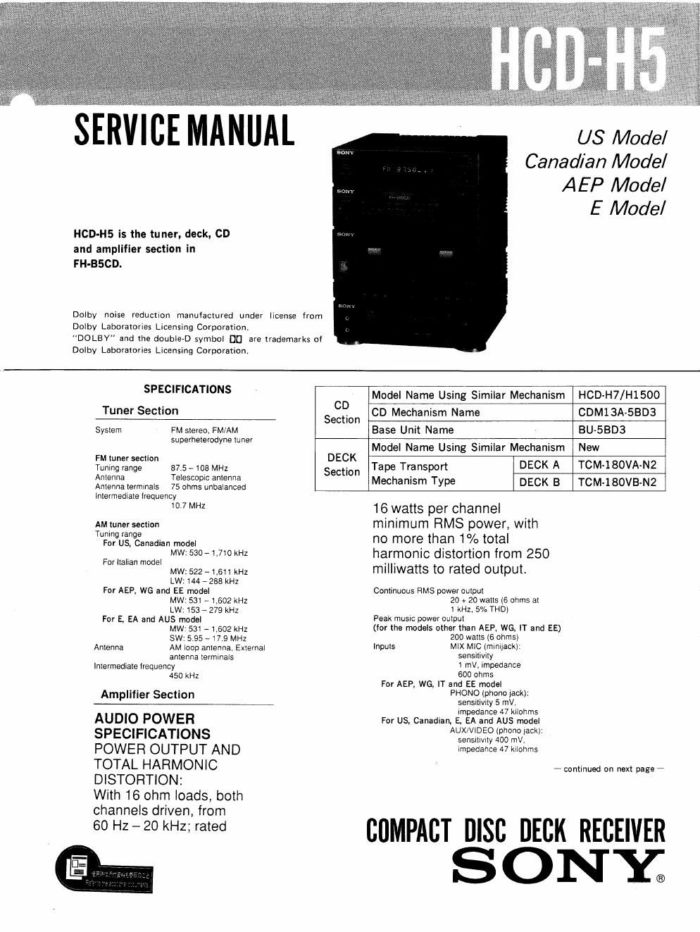
Sony hcd h 5 service manual

This is the 50 pages manual for sony hcd h 5 service manual.
Read or download the pdf for free. If you want to contribute, please mail your pdfs to info@audioservicemanuals.com.

Page: 1 / 50
left right
sony hcd h 5 service manual

Extracted text from sony hcd h 5 service manual (Ocr-read)


Page 1

US Model
Canadian Model
AEP Model

E Model

SERVICE MANUAL

HCD-H5 is the tuner, deck, CD
and amplifier section in
FH-BSCD.

Dolby noise reduction manufactured Under license from
Dolby Laboratories Licensing Corporation
DOLBY and the double-D symbol D0 are trademarks of
Dolby Laboratories Licensing Corporation.

SPEC'F'CM'ONS Model Name Using Similar Mechanism HCD-H7/H1500

Tuner Section Saigon co Mechanism Name CDM13A-SBD3

System FM stereo, FM/AM Base Unit Name BU-5BDB
SUpemeemdyremner C Model Name Using Similar Mechanism New

FMt :1 DE K
Tunirlignfarrigeec on 87.5 , toe MHz Section Tape Transport DECK A TOM-1 SOVA-NZ
Antenna Telescooc antenna Mechanism Type DECK B TCM-l 80VB-N2
Antenna terminals 75 ohms unbalanced

intermediate lrequency
10,7 MHZ

AM tuner section
Tuning range
For US, Canadian model
MW: 530- 1.710 kHz
For Italian model
MW: 522 - 1.611 kHz
LW: 144 - 288 kHz
For AEP, W6 and EE model
MW: 531 -1,602 kHz
LW: 153 a 279 kHz
For E. EA and AUS model
MW: 531 - 1,602 kHz
SW: 595 -17.9 MHZ
AM loop antenna, External
antenna terminals
Intermediate liequency
450 kHz

Antenna

Amplifier Section

AUDIO POWER
SPECIFICATIONS
POWER OUTPUT AND
TOTAL HARMONIC
DISTORTION:

With 16 ohm loads, both
channels driven, from
60 Hz - 20 kHz; rated

16 watts per channel
minimum RMS power, with
no more than 1% total
harmonic distortion from 250
milliwatis to rated output.

Continuous HMS power output
20 + 20 watts (6 ohms at
1 kHz, 5% THD)
Peak musrc power output
(for the models other than AEP, WG, IT and EE)
200 watts (6 ohms)
MIX MIC (mlniiack):
sensitivity
1 mV, impedance
600 ohms
For AEP, WG, IT and EE model
PHONO (phone jack):
sensxtivity 5 mV,
impedance 47 kilohms
For US. Canadian, E, EA and AUS model
AUX/VIDEO (phono lack):
sensittvrty 400 mV,
impedance 47 kilohms

Inputs

7 continued on next page -

COMPACT nisc DECK RECEIVER
SONY;

Page 2

HOD-HS

Outputs HEADPHONES (stereo
miniiacki:
accepts headphones cl
8 ohms or more.
SPEAKER:
accepts speakers of 6 to
16 ohms.

Compact Disc Player Section

System Compact disc digital audio
system

Laser Semiconductor laser

(A480 nm)

Emission duraion:

Continuous

Max. 44.6 mW'

' This ouput is the value

measured at disiace at about

200 mm trom the objective

lens surface on the Optical

Pick-Up Block.

Signal to noise ratio More than 95 dB

Dynamic range More than 90 dB

Harmonic distortion Less than 0.05% (at 1 kHz)

Channel separation More than 90 dB

Laser output

Cassette Deck Section

Recording system 4-track 2-channel stereo
Frequency response (DOLBV NR OFF)
60 v13.000 HZ (:3 dB).
using TYPE I cassette
(Sony HF-S)
60 - H.000 HZ(13 dBJ,
usmg TVPE ii cassette

Wow and llulter 0.1% WRMS 10.3% (DIN)

General
Destination Power Power
requirements consumption
US 120 V AC. 60 Hz 60 watts

Canadian 120 v AC. 60 Hz 80 watts
AERWG,EE 220 V AC, 50160 Hz 60 watts
IT 220V AC, 50H: 60 watts

110-120Voi 60watis
E EA, AUS 220-240 v AC
adjustable. 50/60 Hz

DimenSIons Approx. 615 x 285 x 255 mm
(MM)
(24 h x 11 IA X 10 '/a inches)
incl. protecting parts and
controls
Weight Approx. 11.2 kg (24 lb 11 oz)
Accessories supplied
AM loop antenna 11)
Remote commander (t)
Sony SUM-3 (NS) batteries
(2)
Design and specifications subject to change
Without notice.
Note: We: West Germany, IT: Italian
EA : Saudi Arabia, AUS: Australian
EE : East European

SAFETY-RELATED COMPONENT WARNING"

COMPONENTS IDENTIFIED BY MARK A OR DOTTED
LINE WITH MARK A ON THE SCHEMATIC DIAGRAMS
AND IN THE PARTS LIST ARE CRITICAL TO SAFE
OPERATION. REPLACE THESE COMPONENTS WITH
SONY PARTS WHOSE PART NUMBERS APPEAR AS
SHOWN IN THIS MANUAL OR IN SUPPLEMENTS PUB-
LISHED BY SONY.

TABLE OF CONTENTS

Section Title Pge

1. SERVICING NOTES

2. GENERAL
2-1. Parts Identifications .............................

3. DISASSEMBLY

3-1, Case Assy .......................................
3-2. Power Assy .....................................
3-3, Main Board .....................................
3-4. CD Block ........................................
3-5. Cassette Deck Block ..............................
3-6. VR, Display, Jack, SW Boards ....................

4. MECHANICAL ADJUSTMENTS ..................

5 ELECTRICAL ADJUSTMENTS ....................

G DIAGRAMS
6-1. Semiconductor Lead Layouts ......................
6-2. Circuit Boards Location ..........................
6-3. Printed Wiring Boards

-Tuner/ Deck/ CD Section- ........
6-4. Schematic Diagram-Tuner Section-
6-5. Schematic Diagram-CD Section- ................
6-6. Schematic Diagram-Deck Section- ..............
6-7. Schematic Diagram

-Power/Amplifier/Display Section- ..............
6-8. Printed Wiring Boards ,

-Power/ Amplifier/ Display Section- ..............
6-9. Pin Functions ....................................

7. EXPLODED VIEWS

7-1. Case, Power Supply Block ........................
7-2. Front Panel. Main Board Block
7-3. MD Chassis Block ......... .
7-4. Mechanism Deck Block (1) ........................
7-5. Mechanism Deck Block (2) ........................
7-6. CD Block (1) ....................................
7-7. CD Block (2) ....................................

8. ELECTRICAL PARTS LIST ......................

ATTENTION Au COMPOSANT AYANT RAPPORT
A LA SECURITE!

LES COMPOSANTS IDENTIFIES PAR UNE MAFIOUE A
SUR LES DIAGRAMMES SCHEMATIoUEs ET LA LISTE
DES PIECES SONT CRITIQUES POUR LA SECURITE
DE FONCTIONNEMENT. NE REMPLACER CES coM-
POSANTS QUE PAR DES PIECES SONY DoNT LES
NUMEnos SONT DoNNES DANS ca MANUEL ou
DANS LES SUPPLEMENTS PUBLIES PAR soNY.

_27

.6

.9
.9
,9
10
10
10

11

11

16
17

26
29

33

37
43

47


50
51
52
53

54