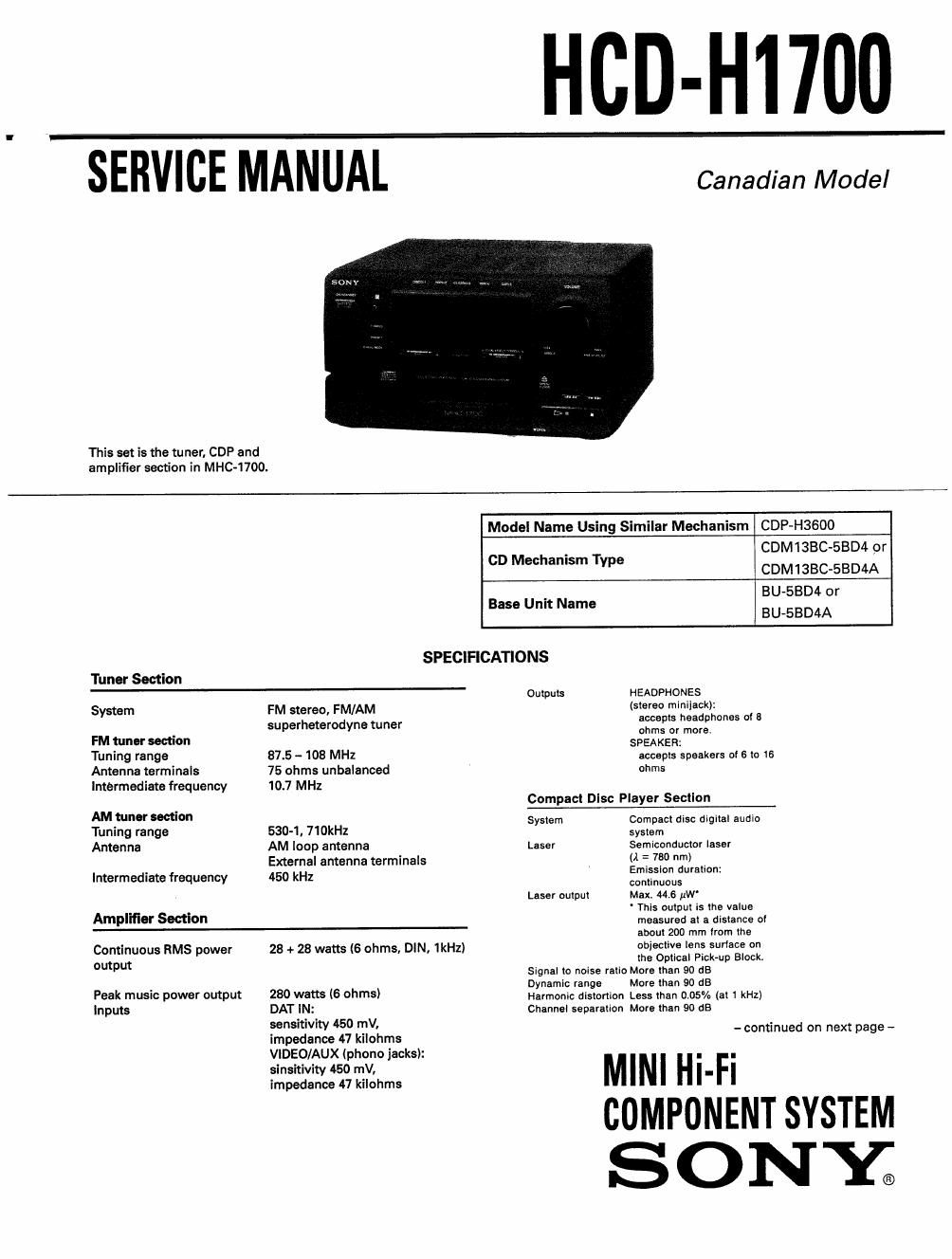
Sony hcd h 1700 service manual

This is the 50 pages manual for sony hcd h 1700 service manual.
Read or download the pdf for free. If you want to contribute, please mail your pdfs to info@audioservicemanuals.com.

Page: 1 / 50
left right
sony hcd h 1700 service manual

Extracted text from sony hcd h 1700 service manual (Ocr-read)


Page 2

HCD-H1700

General

Power requirements 120VAC, 60H:
Powerccnsumption sew-us

Dimensions Tuner/Amplifier/CD player
Approx. 255x125><265 mm Iw/h/d)
(8 7lu>< 5 x 10 lz inches)

Weight Tuner/AmplifierICD Player

Approx. 4.5 kg (9 lb 15 oz)
Supplied accessories

Remote commander (1)

Sony SUM-3 (NS) batteries (2)

AM loop antenna (1)

FM antenna (1)

AC power cord (1)

Speaker cord (2)

Design and specifications subject to change
without notice.

Note

This appliance conforms with EEC Directive
57/308/EEC regarding interference
suppression

SAFETYRELATED COMPONENT WARNINGII

COMPONENTS IDENTIFIED BY MARK A OR DOTTED LINE
WITH MARK A ON THE SCHEMATIC DIAGRAMS AND IN
THE PARTS LIST ARE CRITICAL TO SAFE OPERATION. REPLACE
THESE COMPONENTS WITH SONV PARTS WHOSE PART
NUMBERS APPEAR AS SHOWN IN THIS MANUAL OR IN
SUPPLEMENTS PUBLISHED BY SONY.

ATTENTION AU COMPOSANT AYANT RAPPORT
A LA SECURITEI

LEs COMPOSANTS IDENTIFIE's FAR UNE MAROUE A sun
LEs DIAGRAMMES SCHEMATIOUES ET LA LISTE DES PIECES
SONT camoues POUR LA SECURITE DE FONCTIONNE-
MENT. NE REMPLACER ces COMPOSANTS ous PAR DES
PIEcEs SONY DONT LEs NUMERos SONT DONNEs DANS
CE MANUEL ou DANS LES SUPPLEMENTS PUBLiEs PAR
SONY.

TABLE OF CONTENTS
seam IIILQ Bees
1. SERVICE NOTE
1~1. How to open the Disc Tray when Power Switch

Turns OFF ...................................................... 3

1-2. CD Mechanism
(CDM13BC-SBD4 or CDM1BBC-SBD4A)


and Base Unit (BU-SBD4 or BU-SBDAA) .. 4
2. GENERAL ..
3. DISASSEMBLY 6
4. ADJUSTMENTS
4-1. Test Mode ...................................................... 9
4-2. CD Section Checking ..................................... 10
4-3. Tuner Section Adjustments ............................ 12
5. DIAGRAMS
5-1. Block Diagram ...... 13
5-2. IC Pin Functions .. 17
5-3. Circuit Boards Location .................................. 20
5-4. Waveforms ............................. 21
5-5. Semiconductor Lead Layouts. 23
56. Printed Wiring Boards(DispIay Section) 25
5-7. Schematic Diagram (Display Section) ............ 29
5-8. Printed ering Boards
(Power Amp/Power Supply Section) .............. 33
5-9. Schematic Diagram
(Power Amp/Power Supply Section) .............. 37
5-10. Primed Wirlng Boards (CD Section)
(CDMtaBC-SBD4 and BU-SBD4 Used) ......... 42
5-11. Schematic Diagram (CD Section)
(CDM1380-5BD4 and BU-SBD4 Used) ......... 45
51 2. Printed Wiring Boards (CD Section)
(CDM1ch-5BD4A and BU-SBD4A Used) 48
5-13. Schematic Diagram (CD Section)
(CDM13BC~SBD4A and BU-SBD4A Used) 51
5-14. Printed Vlfirlng Boards (Main/Tuner Section) .. 55
5-15. Schematic Diagram (Main/Tuner Section) ..... 59
6. EXPLODED VIEWS
6-1. Front Panel Section ........................................ 65
6-2. Chassis Section ............... .. 66
6-3. CD Mechanism Section 1 .. 67
6-4. CD Mechanism Section 2 ............................... 68
7. ELECTRICAL PARTS LIST ...... 69