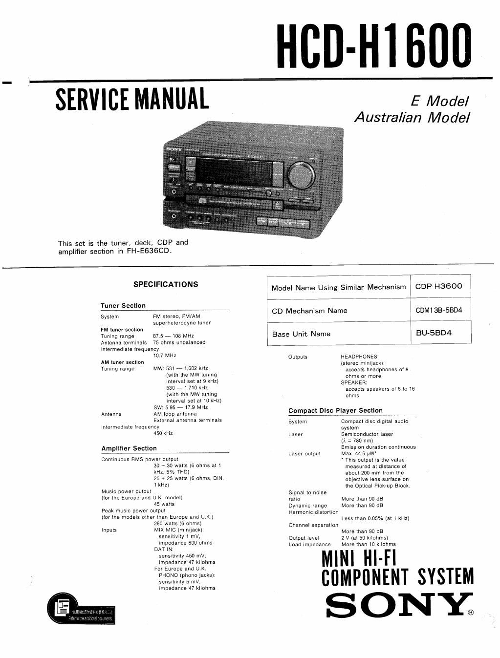
Sony hcd h 1600 service manual

This is the 35 pages manual for sony hcd h 1600 service manual.
Read or download the pdf for free. If you want to contribute, please mail your pdfs to info@audioservicemanuals.com.

Page: 1 / 35
left right
sony hcd h 1600 service manual

Extracted text from sony hcd h 1600 service manual (Ocr-read)


Page 1

HCD-Hl 600

SERVICE MANUAL E Model

Australian Model

This set is the tuner, deck, GDP and
amplifier section in FH-E636CD.

SPECIFICATIONS Model Name Using Similar Mechanism CDP-H3GOO

Tuner Section

Sysem FM slaw FM/AM CD Mechanism Name CDM13B-SBD4

superneterodyne tuner

FM tuner section
Tunlng range 87.5 ,103 MHz Base Unit Name BU-5BD4

Antenna terminals 75 ohms unbalanced

Intermediate lrequency

0 7 MHZ Outputs HEADPHONES
(stereo minilack):

AM tuner section

Tuning range MW: 531 - 160? kHz accepts headphones at s
(with the MW tuning ohms or more.
Interval set at 9 kHz) SPEAKER:

530 - l.710 kHz

(with the MW tuning

interval set at lo kHz)
SW: 5 95 - 17.9 MHZ

accepts speakers ol 6 to 16
ohms

Compact Dlsc Player Section

Antenna AM loop antenna
External antenna terminals System Compact disc digital audio

Intermediate lrequency system
450 kHl Laser Semiconductor laser

(A = 780 nm)

Amplilier Section Emission duration continuous

----- Laser output Max. 446 iiW'

Continuous RMS power output ' This output ts the value
30 + 3:) watts (6 ohms at l measured at distance at
kHz. 5/0 THD) about 200 mm item the
25 + 25 watts (6 ohms, DIN- objective lens surtace on

> 1 kHz) the Optical Pick-up Block.

Music power outle Signal to noise

(lor the Europe and UK. model) ram, More than 90 dB

45 watts Dynamic range More than 90 dB

Peak musw Dowel Output Harmonic distortion

(tor the models other than Europe and UK.) Less than 0.05% (at 1 kHz)
280 watts (6 ohm) Channel separation

inputs MIX MIC tminiiackJ: More than 90 dB

sensrtiVity 1 mV, Output level 2 V (at 50 kilohmsj

Dgflfizfian 50° °th Load impedance More than 10 kilohms

sensitivity 450 mil,
impedance A7 kilohms '

For Europe and UK

PHONO (phono jacks):
sensmvity 5 mV.
impedance 47 kilohrns

Page 2

HCD-H1600J

TABLE OF CONTENTS

Section Title m
1' GENERAL ............................................. 3
2' DISASSEMBLY .......................................... 5
3. ADJUSTMENTS
3-I Mechanical Adjustments ------------------------- 8
32 Electrical Adjustments -------------------------- 8
4. DIAGRAMS
4_1_ Blockdiagram .................................... II
4-2. Circuit Boards Location ------------------------ 13
4-3. Semiconductor Lead Layouts ---------------------- 14
4-4. Printed Wiring Boards
-_ Audio Section _ (Former Type) -------------- 15
4'5. Printed Wiring Boards
- Audio Section - (New Type) ---------------- 20
4-6. Schematic Diagram
__ Audio Section _ .......................... 25
47. Printed Wiring Boards
__ CD Section? .............................. 30
4-& Schematic Diagram
_ CD Sectiow .............................. 32
4-9. Waveforms ...................................... 35
5. EXPLODED VIEWS
5-1. Front Panel Section ---------------------------- 36


5-2. Chassis Section --------

5~3. CD Mechanism Section-1"

5-4. CD Mechanism Section-2 -------------------- 39
6. ELECTRICAL PARTS LIST ------------------------------- 40

SAFETYrRELATED COMPONENT WARNINGI!

COMPONENTS IDENTIFIED BY MARK A OR DOTTED
LINE WITH MARK A ON THE SCHEMATIC DIAGRAMS
AND IN THE PARTS LIST ARE CRITICAL TO SAFE
OPERATION. REPLACE THESE COMPONENTS WITH
SONY PARTS WHOSE PART NUMBERS APPEAR AS
SHOWN IN THIS MANUAL OR IN SUPPLEMENTS PUB-
LISHED BY SONY.