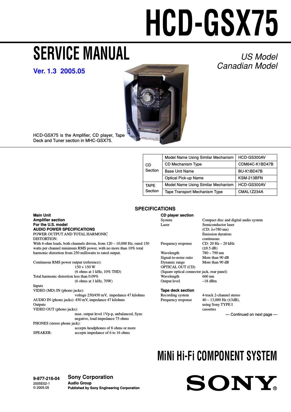
Sony hcd gsx 75 service manual

This is the 68 pages manual for sony hcd gsx 75 service manual.
Read or download the pdf for free. If you want to contribute, please mail your pdfs to info@audioservicemanuals.com.

Page: 1 / 68
left right
sony hcd gsx 75 service manual

Extracted text from sony hcd gsx 75 service manual (Ocr-read)


Page 1

HCD-GSX75

SERVICE MANUAL

Ver. 1.3 2005.05

HCD-GSX75 is the Amplifier, CD player, Tape
Deck and Tuner section in MHC-GSX75.

US Model
Canadian Model

Model Name Using Similar Mechanism HCD-GS300AV
CD CD Mechanism Type CDM64C-K1BD47B
Section Base Unit Name BU-K1BD47B
Optical Pick-up Name KSM-213BFN
TAPE Model Name Using Similar Mechanism HCD-GSBDOAV
Section Tape Transport Mechanism Type CMAL12234A

SPECIFICATIONS

Main Unit

Amplifier section

For the U.S. model

AUDIO POWER SPECIFICATIONS

POWER OUTPUT AND TOTAL HARMONIC

DISTORTTON:

With 6-ohm loads, both channels driven, from 120 - 10,000 Hz; rated 150
watts per channel minimum RMS power, with no more than 10% total
harmonic distortion from 250 milliwatts to rated output.

Continuous RMS power output (reference):
150 + 150 W
(6 ohms at 1 kHz, 10% THD)
Total harmonic distortion less than 0.09%
(6 ohms at 1 kHz, 70W)
Inputs
VIDEO (MD) IN (phono jacks):
voltage 250/450 mV, impedance 47 kilohms
AUDIO IN (phono jacks): 450 mV, impedance 47 kilohms
Outputs
VIDEO OUT (phono jacks):
max. output level 1Vp-p, unbalanced, Sync
negative, load impedance 75 ohms
PHONES (stereo phone jack):
accepts headphones of 8 ohms or more

SPEAKER: accepts impedance of 6 to 16 ohms
9-877-216-04 Sony corporation

2005E0271 Audio Group

©2005.05 Published by Sony Engineering Corporation

CD player section
System
Laser

Compact disc and digital audio system
Semiconductor laser

(CD: 1:780 nm)

Emission duration:

continuous
Frequency response CD: 20 Hz - 20 kHz
(:05 dB)
Wavelength 780 - 790 nm
Signal-to-noise ratio More than 90 dB
Dynamic range More than 90 dB
OPTICAL OUT (CD)
(Square optical connector jack, rear panel)
Wavelength 660 nm
Output level -1 8 dBm

Tape deck section
Recording system
Frequency response

4-track 2-channel stereo
40 -13,000 Hz (t3dB),
using Sony TYPE I
cassettes
- Continued on next page -

Milli Hi-Fi COMPONENT SYSTEM
S ONE;

Page 2

HCD-GSX75
Ver1.1 2003.09

Tuner section
FM stereo, FM/AM superheterodyne tuner
FM tuner section
Tuning range
Antenna

87.5 - 108.0 MHz
FM lead antenna

Antenna terminals 75 ohms unbalanced
Intermediate frequency 10.7 MHz
AM tuner section
Tuning range 530 - 1,710 kHz
(with the tuning interval

set at 10 kHz)

531 - 1,710 kHz

(with the tuning interval

set at 9 kHz)
Antenna AM loop antenna, external antenna terminal
Intermediate frequency 450 kHz

General
Power requirements: 120 V AC, 60 Hz
Power consumption: 150 W
Dimensions (w/h/d) incl. projecting parts and controls Amplifier/Funer/
Tape/CD section:
Approx. 280 x 326 x 490 mm
Mass: Approx. 11.4 kg
Supplied accessories Remote (1)
size AA (R6) batteries (2)
AM loop antenna (1)
FM lead antenna (1)

Design and specifications are subject to change
without notice

TABLE OF CONTENTS
1_ SERVICING NOTES ,,,,,,,,,,,,,,,,,,,,,,,,,,,,,,,,,,,,,,,,,,,,,,,,,,,,,,, 4 7_ DIAGRAMS
7-1. Circuit Boards Location - -22
2_ GENERAL .......................................................................... 5 7-2. Block Diagrams -
- CD Section - --
3_ DISASSEMBLY ................................................................ 7 * Tuner/Tape DBCk 560mm 4
- INPUT/EVR Section -

3-1. Top Cabinet
3-2. Front Cabi ASSY
3-3. Back Panel ASSY
3-4. Main Board
3-5. Amp Board
3-6. Power Board-
3-7. Holder (LED-S), Middle (R), Power Bracket
3-8. CD Mechanism Deck (CDM64C-K1BD47B) ------------ 11

>8
-8
9

3-9. Base Unit (BU»K1BD47B),

D-Sensor (OUT) Board, T-Sensor Board -------------------- 12
3-10.D-Sensor (IN) Board, Load SW Board,

LT Motor Board

3-11. CD LED Board
3-121BU Holder ASSY
3-13. CD Board, Optical Pick-up (KSM-213BFN) >>>>>>>>>>>>>> 14
3-141 RX-Base PC Board ASSY,

Mechanical Deck (CMAL12234A),

Cassette Holder rrrrrrrrr
3-15. Game Board, H/P Board
3-16. Display Board ............

.. 14
15
15

3-17.KEY (2) Board, CD Sync Button 16
3-18.KEY Board, Wireless Board ........................................ 16
4_ TEST MODE ,,,,,,,,,,,,,,,,,,,,,,,,,,,,,,,,,,,,,,,,,,,,,,,,,,,,,,,,,,,,,,,,,,,, 17
5. MECHANICAL ADJUSTMENTS ............................. 18
6. ELECTRICAL ADJUSTMENTS .............................. 18

~Amp Section _

- Display/Power Supply Section -
7-3. Printed Wiring Board - CD Section --
7-4. Schematic Diagram - CD Section -..
7-5. Printed Wiring Board

_ CD Motor/Sensor Section _ ..................................... 30
7-6. Schematic Diagram

- CD Motor/Sensor Section -
7-7. Printed Wiring Board - Main Section -
7-8. Schematic Diagram ~ Main Section (1/3)
7-9. Schematic Diagram - Main Section (2/3)
7-10. Schematic Diagram - Main Section (3/3)
7-11. Printed Wiring Board - Amp Section
7-12. Schematic Diagram ~ Amp Section A
7-13.Printed Wiring Board - Display Section -
7-14. Schematic Diagram - Display Section -
7-15. Printed Wiring Board - Key Section -
7-16. Schematic Diagram ~ Key Section
7-17. Printed Wiring Board - Power Section -
7-18. Schematic Diagram - Power Section
7-19.IC Block Diagrams
7.20, IC Pin Function Description ........................................ 45

>27

8. EXPLODED VIEWS
3.1, General Section ........................................................... 51
8-2. Front Panel Section
8-3. Chassis Section rrrrr
8-4. Mechanism Deck Section-1 (CDM64C-K1BD47B) 54

8-5. Mechanism Deck Section-2 (CDM64C-K1BD47B .55
8-6. Base Unit Section (BU-K1BD47B) --------------------------- 56
9. ELECTRICAL PARTS |_|ST ....................................... 57