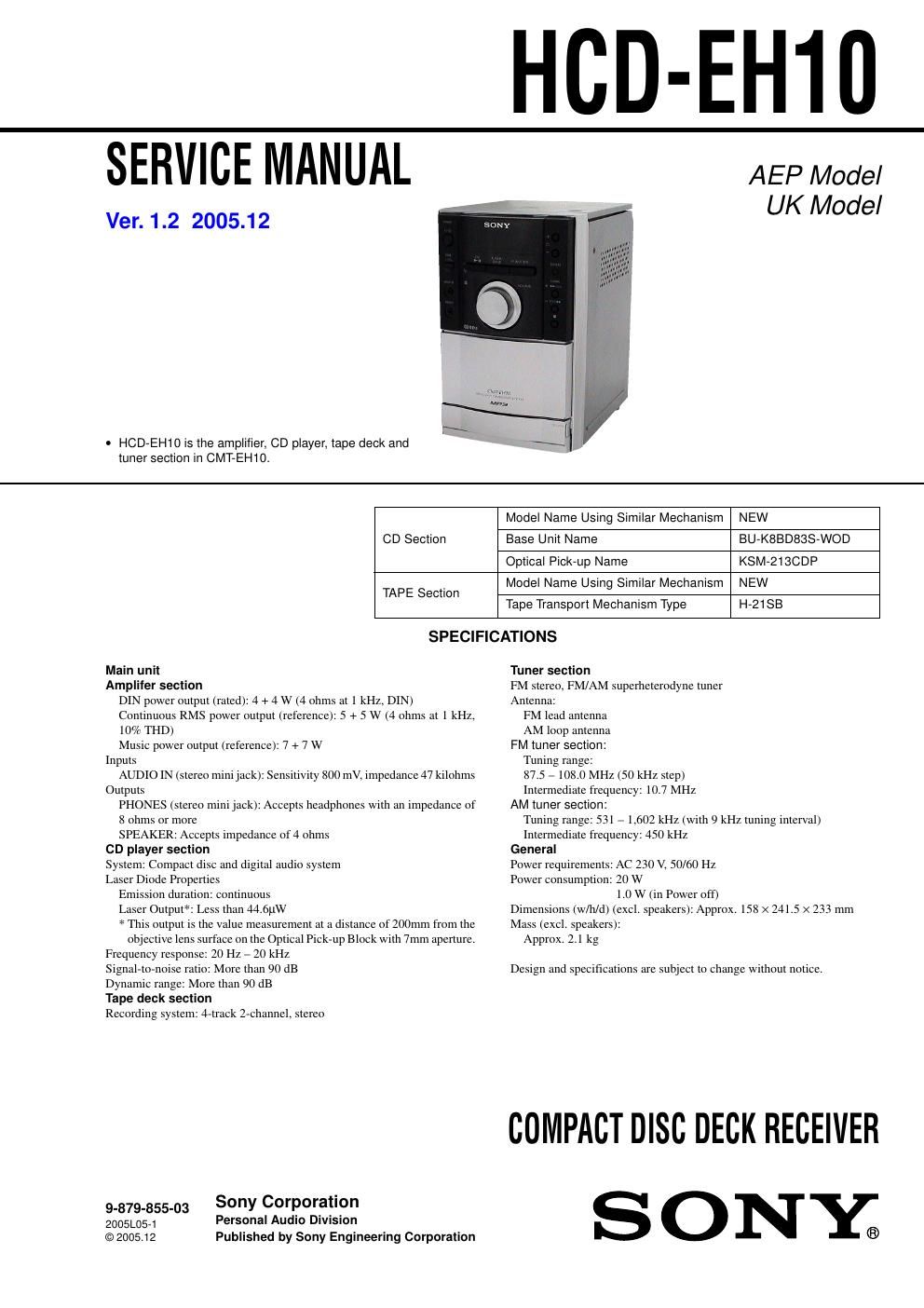
Sony hcd eh 10 ver 1 2

This is the 58 pages manual for sony hcd eh 10 ver 1 2.
Read or download the pdf for free. If you want to contribute, please mail your pdfs to info@audioservicemanuals.com.

Page: 1 / 58
left right
sony hcd eh 10 ver 1 2

Extracted text from sony hcd eh 10 ver 1 2 (Ocr-read)


Page 1

HCD-EH10

SERVICE MANUAL

Ver. 1.2 2005.12

- HOD-EH10 is the amplifier, CD player, tape deck and
tuner section in CMT-EH10.

AEP Model
UK Model

Model Name Using Similar Mechanism NEW

CD Section Base Unit Name BU-KBBDSSS-WOD
Optical Pick-up Name KSM-21BCDP
_ Model Name Using Similar Mechanism NEW
TAPE Section
Tape Transport Mechanism Type H-21 SB

SPECIFICATIONS

Main unit
Ampliter section
DIN power output (rated): 4 + 4 W (4 ohms at 1 kHz, DIN)
Continuous RMS power output (reference): 5 + 5 W (4 ohms at 1 kHz.
10% THD)
Music power output (reference): 7 + 7 W
Inputs
AUDIO IN (stereo minijack): Sensitivity 800 mV, impedance 47 kilohms
Outputs
PHONES (stereo minijack): Accepts headphones with an impedance of
8 ohms or more
SPEAKER: Accepts impedance of 4 ohms
CD player section
System: Compact disc and digital audio system
Laser Diode Properties
Emission duration: continuous
Laser Output": Less than 44.6t1W
* This output is the Value measurement at a distance of 200mm from the
objective lens surface on the Optical Pick-up Block with 7mm aperture.
Frequency respon 20 Hz - 20 kHz
Signal-to-noise ratio: More than 90 dB
Dynamic range: More than 90 dB
Tape deck section
Recording system: 4-track 2-channel, stereo

Sony Corporation

9-879-855-03
2001054 Personal Audio Division
©2005.12 Published by Sony Engineering Corporation

Tuner section
FM stereo, FM/AM superheterodyne tuner
Antenna:
FM lead antenna
AM loop antenna
FM tuner section:
Tuning range:
87.5 - 108.0 MHz (50 kHz step)
Intermediate frequency: 10.7 MHz
AM tuner section:
Tuning range: 531 - 1,602 kHz (with 9 kHz tuning interval)
Intermediate frequency: 450 kHz
General
Power requirements: AC 230 V, 50/60 Hz
Power consumption: 20 W
1.0 W (in Power off)
Dimensions (w/h/d) (excl. speakers): Approx. 158 X 241.5 x 233 mm
Mass (excl. speakers):
Approx. 2.1 kg

Design and specifications are subject to change without notice.

COMPACT DISC DECK RECEIVER
S 0 NY;

Page 2

HCD-EH10

Notes on chip component replacement
0 Never reuse a disconnected chip component.
0 Notice that the minus side of a tantalum capacitor may be
damaged by heat.

Flexible Circuit Board Repairing
0 Keep the temperature of the soldering iron around 270 C
during repairing.
0 Do not touch the soldering iron on the same conductor of the
circuit board (within 3 times).
0 Be careful not to apply force on the conductor when soldering
or unsoldering.

CAUTION

Use of controls or adjustments or performance of procedures
other than those specified herein may result in hazardous radiation
exposure.

The following caution label is located inside the uniti

This appliance is classified
as a CLASS 1 LASER
product.

This label is located on the
rear exterior.

cuss t LASER PRODucT
LuoKAN t LASER LAlTE

KLASS t LASER APPARAT

SAFETY-RELATED COMPONENT WARNING !!

COMPONENTS IDENTIFIED BY MARK A OR DOTTED LINE
WITH MARK A ON THE SCHEMATIC DIAGRAMS AND IN
THE PARTS LIST ARE CRITICAL TO SAFE OPERATION.
REPLACE THESE COMPONENTS WITH SONY PARTS WHOSE
PART NUMBERS APPEAR AS SHOWN IN THIS MANUAL OR
IN SUPPLEMENTS PUBLISHED BY SONY.

2

3.

3.1_
3-2.
373.

7.
771.
772.
773.
74.
775
776.
777.
78.
779.
7710.
7711.

8.

3.1_
8-2.
84.

9.

TABLE OF CONTENTS

SERVICING NOTES 3
GENERAL 4
DISASSEMBLY

Disassembly Flow .. 6
Rear Cabinet Section . 6
Front Cabinet Section, Top Cabinet Section and

MAIN Board ...................................... 7
Mechanical Deck (HAZISB) ................. 7
Base Unit Section (BU-K8BD83S-WOD) 8
Optical Pick-up Block (KSM-213CDP) .......................... 8
TEST MODE .. 9

MECHANICAL ADJUSTMENTS

ELECTRICAL ADJUSTMENTS ..

10

DIAG RAMS

Block Diagram 7 CD SERVO Section 7
Block Diagram 7 TUNER Section 7 .
Block Diagram 7 MAIN Section 7
Printed Wiring Board 7 CD Board
Schematic Diagram 7 CD Board 7
Printed Wiring Boards 7 MAIN Section 7
Schematic Diagram 7 MAIN Section (l/3) 7.
Schematic Diagram 7 MAIN Section (2/3)
Schematic Diagram 7 MAIN Section (3/3)
Printed Wiring Board 7 PANEL Board
Schematic Diagram 7 PANEL Board 7

EXPLODED VIEWS

Overall Section ....... 34
Front Cabinet Section 35
Top Cabinet Section ............................. 36
Base Unit Section (BUAKSBD83S-WOD) 37

ELECTRICAL PARTS LIST ................................ 38