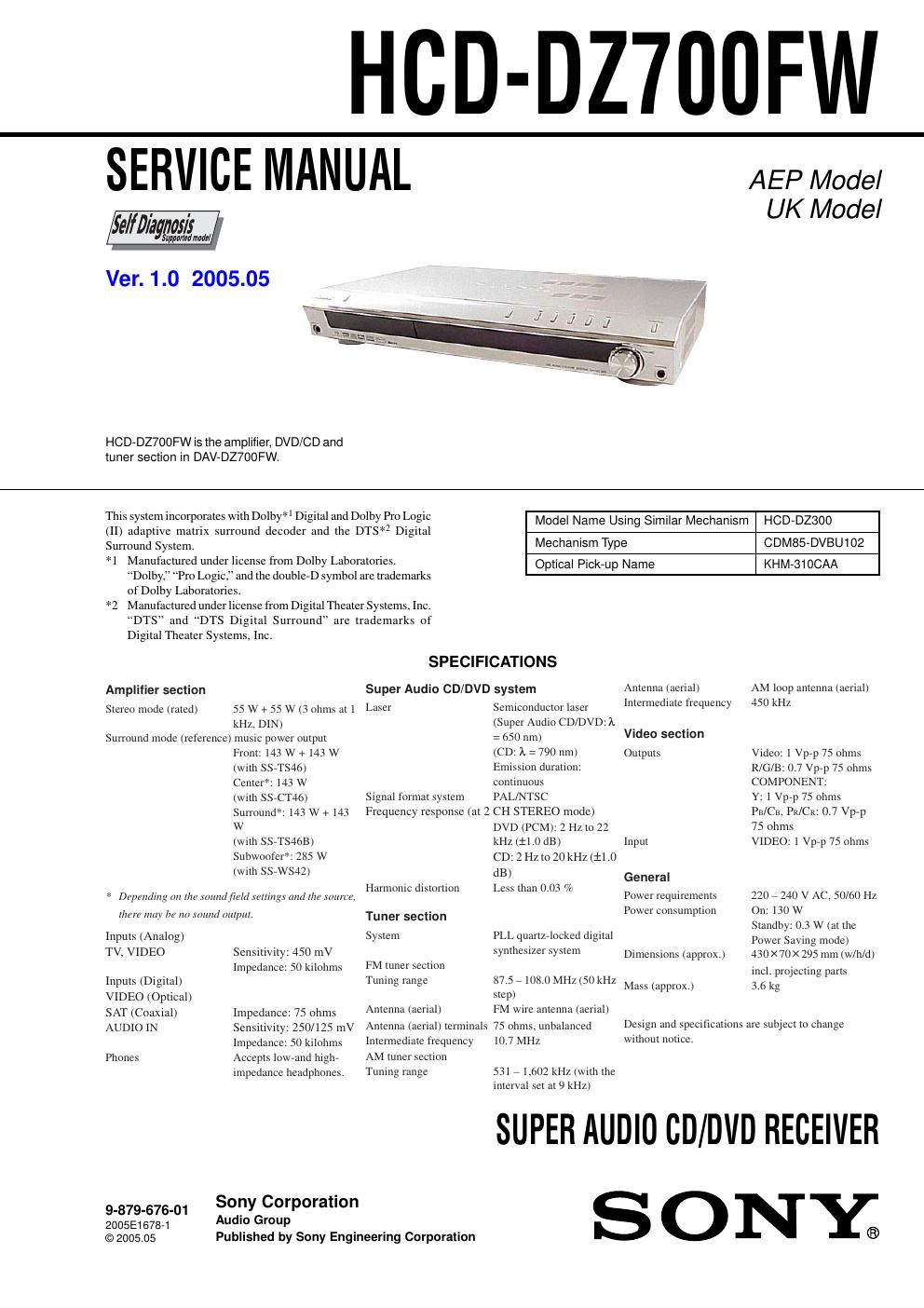
Sony hcd dz 700 fw service manual

This is the 90 pages manual for sony hcd dz 700 fw service manual.
Read or download the pdf for free. If you want to contribute, please mail your pdfs to info@audioservicemanuals.com.

Page: 1 / 90
left right
sony hcd dz 700 fw service manual

Extracted text from sony hcd dz 700 fw service manual (Ocr-read)


Page 1

HCD-DZ700FW

SERVICE MANUAL

ie/ffl/ayrmm

Ver. 1.0 2005.05

AEP Model
UK Model

HCD-DZ700FW is the amplifier, DVD/CD and
toner section in DAV-DZ7OOFW.

Surround System.
*1

of Dolby Laboratories.
*2

stem incorporates with Dolby*| Digital and Dolby Pro Logic
(II) adaptive matrix surround decoder and the DTS*Z Digital

Manufactured under license from Dolby Laboratories.
Dolby," "Pro Logic, and the double-D symbol are trademarks

Model Name Using Similar Mechanism HOD-D2300
Mechanism Type CDM85-DVBU102
Optical Pick-up Name KHM-310CAA

Manufactured under license from Digital Theater Systems, Inc.

DTS and DTS Digital Surround" are trademarks of

Digital Theater Systems, Inc.

Amplitier section
Stereo rnotle (rated) 55 W + 55 W (3 ohms at l
kllz. DIN)
Surround mtJLIc (reterenee) musre power output
Front: 143 W +143 W
(with SSVTS46)
Center*: 143 W
(with SSVCT46)
Sun'ound*' 143 W + 143
W
(with SSVTS46B)
Subwoolefi: 285 W
(with SSVWS42)

» Depending on [He round/tam setli/tgx and me mama.

I/Itlt may be an round (MI/7m.

Inputs (Analog)
TV, VIDEO Sensitrvity: 450 mV
Impedance: 50 krlohms

Inputs (Digital)

VIDEO (Optical)

SAT (Coaxial) Impedance: 75 ohms

AUDIO IN Sensitivity: 250/[25 mV
Impedance: 50 krlohms

Phones Accepts Iowrand highr
impetlanee headphones.

945794575431 Sony Corporatton

200596734 Audio GmUP

© 2005.05

Published by Sony Engineering Corporation

SPECIFICATIONS
Super Audio CD/DVD system

Semiconductor laser
(Super Audio CD/DVD: )t
: 650 nm)

(CD. A. : 790 nm)
Emission duration:

Laser

continuous
Signal format system PAL/NTSC
Frequency response (at 2 CH STEREO mode)
DVD (PCM): 2 II; to 22
kIIL (:1!) dB)
CD: 2 Hz to 20 kHz (ii .0
dB)
IIarmonic distortion Less than 0.03 Yr

Tuner section
System PLL quartetnekea digrtal
synthesizer s) stem

FM tuner section

87.571080MIIUSO RIIL
step)

FM wrre antenna (aerial)

Tuning range

Antenna (aerial)
75 ohms, unbalanced
10.7 MIIl

Antenna (aerial) terminals
Intennediate frequency
AM tuner ctiou

Tuning range

53171.602 kIIL (with the
interval set at 9 kHz)

Antenna (aerial)
Intermediate frequency

AM loop antenna (aerial)
450 kIlz

Video section

Outputs Video: 1 Vprp 75 ohms
R/GIB' 0.7 Vprp 75 ohms
COMPONENT:
Y: 1 Vprp 75 ohms
Fri/CB, Pr/Cr: 0.7 Vp-p
75 ohms

Input VIDEO: 1 Vprp 75 ohms

General

Pow requirements 220 7 240 V AC. 50/60 II:

On: 130 W

Standby ()3 W (at the
Power Saving mode)

430 X 70X 295 mm (w/h/d)
incl. projecting parts

3.0 kg

Power consumption

Dimensions (approx)

Mass (approx)

Design and specifications are subject to change
wrthunt notice.

SUPER AUDIO CD/DIID RECEIVER

SONY®

Page 2

HCD-DZ700FW

Laser component in this product is capable of emitting radiation
exceeding the limit for Class 1.

This appliance is classified as
CLASS 1 LASER PRODUCT 1 CLASS 1 LASER PmduCl-
LUOKAN 1 LASERLAITE The CLASS 1 LASER
PRODUCT MARKING is
located on the rear exterior.

KLASS i LASERAPPAFIAT

CAUTION

Use of controls or adjustments or performance of procedures
other than those specified herein may result in hazardous radiation
exposure.

Notes on chip component replacement
0 Never reuse a disconnected chip component.
0 Notice that the minus side of a tantalum capacitor may be
damaged by heat.

Flexible Circuit Board Repairing
0 Keep the temperature of the soldering iron around 270 °C
during repairing.
0 Do not touch the soldering iron on the same conductor of the
circuit board (within 3 times).
0 Be careful not to apply force on the conductor when soldering
or unsoldering.

UNLEADED SOLDER

Boards requiring use of unleaded solder are printed with the lead-

free mark (LF) indicating the solder contains no lead.

(Caution: Some printed circuit boards may not come printed with
the lead free mark due to their particular size)

: : LEAD FREE MARK
Unleaded solder has the following characteristiCs.

O Unleaded solder melts at a temperature about 40 °C higher
than ordinary solder.
Ordinary soldering irons can be used but the iron tip has to be
applied to the solderjoint for a slightly longer time.
Soldering irons using a temperature regulator should be set to
about 350 °C.
Caution: The printed pattern (copper foil) may peel away if
the heated tip is applied for too long, so be careful!
0 Strong viscosity
Unleaded solder is more viscouAs (sticky, less prone to flow)
than ordinary solder so use caution not to let solder bridges
occur such as on IC pins, etc.
0 Usable with ordinary solder
It is best to use only unleaded solder but unleaded solder may
also be added to ordinary solder.

SAFETY-RELATED COMPONENT WARNING I!

COMPONENTS IDENTIFIED BY MARK A OR DOTTED LINE
WITH MARK A ON THE SCHEMATIC DIAGRAMS AND IN
THE PARTS LIST ARE CRITICAL TO SAFE OPERATION.
REPLACE THESE COMPONENTS WITH SONY PARTS WHOSE
PART NUMBERS APPEAR AS SHOWN IN THIS MANUAL OR
IN SUPPLEMENTS PUBLISHED BY SONY.

2

MODEL IDENTIFICATION

- Rear Panel -
l%l l=l
Parts No.
Model Part No.
AEP and UK models 2-588-157-0D
RU model 2-588-157-1l]
- Abbreviation
RU : Russian model.