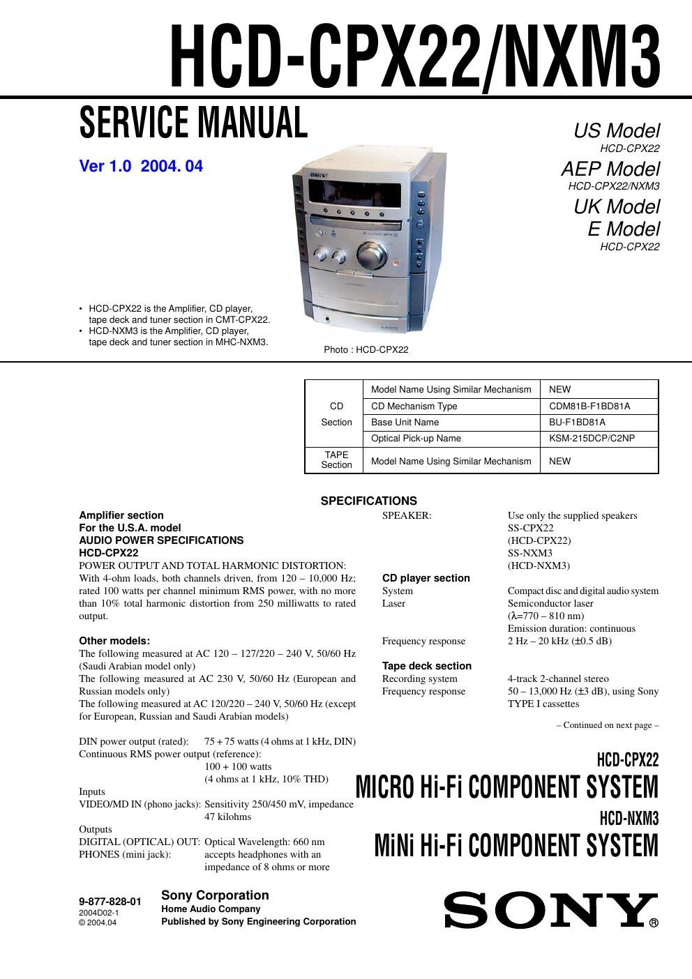
Sony hcd cp x22

This is the 68 pages manual for sony hcd cp x22.
Read or download the pdf for free. If you want to contribute, please mail your pdfs to info@audioservicemanuals.com.

Page: 1 / 68
left right
sony hcd cp x22

Extracted text from sony hcd cp x22 (Ocr-read)


Page 2

HCD-CPX22/NXM3

Tuner section
FM stereo, FM/AM superheterodyne tuner
FM tuner section
Tuning range
U.S.A. model:
Russian model:

87.5 7 108.0 MHz (100-kHz step)
65.0 7 74.0 MHz (lOAkHz step)
(There is no stereo effect)

87.5 7 108.0 MHz (50-kHz step)
FM lead antenna

75 ohms unbalanced

10.7 MHz

Other models:
Antenna
Antenna terminals
Intermediate frequency
AM tuner section
Tuning range
Pan-American model: 530 7 1,710 kHz
(with the tuning interval set at 10 kHz)
53171,710 kHz
(with the tuning interval set at 9 kHz)
European, Russian and Saudi Arabian models:

53171,602 kHz

(with the tuning interval set at 9 kHz)

Other models: 531 7 1,602 kHz
(with the tuning interval set at 9 kHz)
530 71,710 kHz
(with the tuning interval set at 10 kHz)
Antenna AM loop antenna

Antenna terminals External antenna terminal

Intermediate frequency 450 kHz
General

Power requirements

U.S.A. model: 120 V AC, 60 Hz

European and Russian models:

230 V AC, 50/60 Hz

120 7127 V or 220 7 240 V AC,
50/60 Hz

Adjustable with voltage selector
120 V, 220 7 240 V AC, 50/60 Hz
Adjustable with voltage selector

Saudi Arabian model:

Other models:

Power consumption
U.S.A. model: 65 watts
European and Russian models: 65 watts
0.3 watts (in Power Saving mode)
Other models: 65 watts
Dimensions (w/h/d) incl. projecting parts and controls
Amplifier/Tuner/Tape/CD section:
Approx. 230 x 292 x 355 mm
Mass
Amplifier/Tuner/Tape/CD section:
Approx. 6.1 kg
Remote Commander (1)
Size AA (R6) batteries (2)
AM loop antenna (1)
FM lead antenna (1)
Speaker pads (8)
Speaker cords

Supplied accessories

Design and specifications are subject to change without notice.

SAFETY CH ECK-OUT

After correcting the original service problem, perform the following
safety checks before releasing the set to the customer:

Check the antenna terminals, metal trim, metallized knobs, screws,
and all other exposed metal parts for AC leakage. Check leakage as
described below.

LEAKAGE

The AC leakage from any exposed metal part to earth ground and
from all exposed metal parts to any exposed metal part having a
return to ch s, must not exceed 0.5 mA (500 microamperes).
Leakage current can be measured by any one of three methods.

1. Acommercial leakage tester, such as the Simpson 229 or RCA
WT-540A. Follow the manufacturers instructions to use these
instruments.

2. A battery-operated AC milliammeter. The Data Precision 245
digital multimeter is suitable for this job.

3. Measuring the voltage drop across a resistor by means of a
VOM or battery-operated AC voltmeter. The limit" indication
is 0.75 V, so analog meters must have an accurate low-voltage
scale. The Simpson 250 and Sanwa SH-63Trd are examples
ofa passive VOM that is suitable. Nearly all battery operated
digital multimeters that have a 2V AC range are suitable. (See

Fig. A)
To Exposed Metal
Parts on Set
AC
0. 15 F :: > [/ Voltmeter
11 1.5 k :2 (a 75 V)
5 Earth Ground
Fig. A. Using an AC voltmeter to check AC leakage.