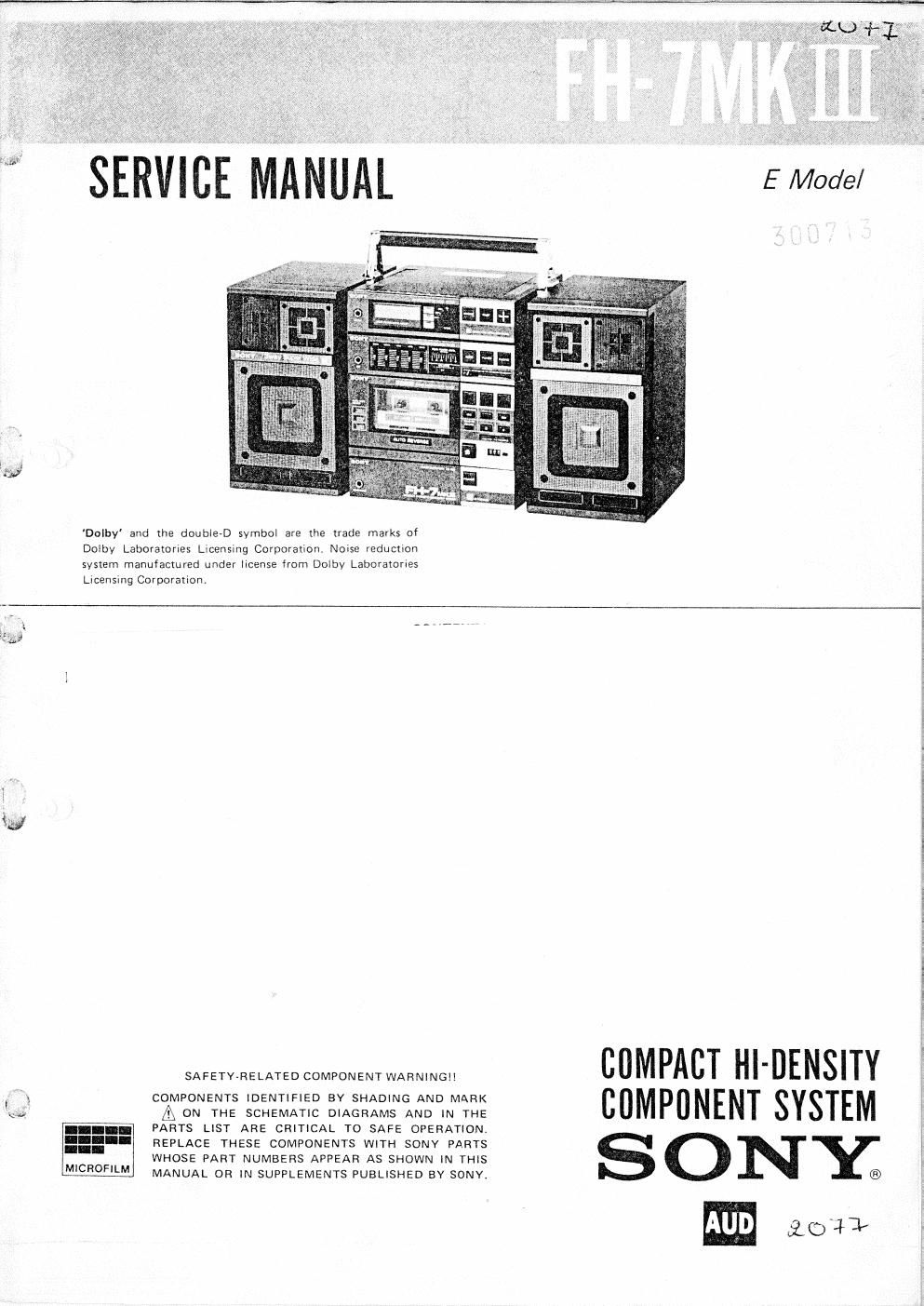
Sony fh 7 mk2 service manual

This is the 28 pages manual for sony fh 7 mk2 service manual.
Read or download the pdf for free. If you want to contribute, please mail your pdfs to info@audioservicemanuals.com.

Page: 1 / 28
left right
sony fh 7 mk2 service manual

Extracted text from sony fh 7 mk2 service manual (Ocr-read)


Page 1

Dolby' and the doublerD symboi are the Trade marks of
Dmby Laboratories Licensmg Corporahon. Noise reductxon
svslem manufactured under IICEHSE from Dolby Laboratories
Licensing Corporanon.

Eth#

by

MICROFILM

SAFETY-RELATED COMPONENT WARNINGII

COMPONENTS IDENTIFIED BY SHADING AND MARK
A ON THE SCHEMATIC DIAGRAMS AND IN THE
PARTS LIST ARE CRITICAL T0 SAFE OPERATION.
REPLACE THESE COMPONENTS WITH SONY PARTS
WHOSE PART NUMBERS APPEAR AS SHOWN IN THIS
MANUAL OR IN SUPPLEMENTS PUBLISHED BY SONV.

COMPACT HI-OENSITY
COMPONENT SYSTEM

SONY;

£04}

Page 2

FH-7 MKIII FH-7 MKIH

SECTION 2 ST-78 111 ST-78 111
ADJUSTM ENTS
MW/SW SECTION
MW Slow Speed Action Level Adjustment
Setting: Setting: VOM (DC range}
BAND selector switch: MW, SW1 or SW2 (conductor side)

AM CH. SPACE switch: 9kHz

CNJ302 VTVM

AM I! signal
generator

Put the lead-wire
/ antenna close to
O the set.

§- |5+

Procedure:
3009; almintuge 1. Set BAND selector switch ($1) to MW. Confirm
m Hat/on y . .
00,. signal that the unit is detuned.
2. Adjust RT401 so that the collector voltage of
0 Repeat the procedures in each adjustment 0605 is 4.0- 5.0V.
several times, and the OSC voltage and tracking
adjustments should be finally done by the
trimmer capacitors. RT401

MW IF ADJUSTMENT

Adjust for a maximum reading

MW/sw1/sw2 osc Voltage Adjustment °" VTVM-
Procedure: T40] 450
Setting: >
°°"d°°' "19) .. 1. Set BAND selector switch (81) to MW.
VOM 2. Push TUNING (+, -) button for S3lkHz. Adjust
(DCrange) L402 for 1.0 - 1.1V VOM reading. MW TRACKING ADJUSTMENT
3. Push the button for 1,602kHZ. Adjust CT406 AdiUS [0 a maximum reading
/ for 8.9 - 9.0V VOM reading. ° VTVM~
+ T403 1,404kH
o-- 4. Set BAND selector switch (51) to SW1. C l
- L401 603kHz
5. Push TUNING (+, -) button for 3.2MHZ. Adjust

L404 for 1.0 - 1.1V VOM reading.
6. Push the button for 7.3MHz. Adjust CT405

for 8.9 ~- 9.0V VOM reading. SW1 TRACKING ADJUSTMENT

Adjust for a maximum reading

7. Set BAND selector switch (SI) to SW2.
on VTVM.

8. Push TUNING (+, -) button for 9.5MHz. Adjust -1,402 65MB:

L406 for 1.0 - l.1V VOM reading.

L403 3.5MHZ

9. Push the button for 21.75MHz. Adjust CT404 for
8.9 - 9.0V VOM reading.

SW2 TRACKING ADJUSTMENT

Adjust for a maximum reading

on VTVM.

CT401 ZOMHZ

L405 L405 IOMHZ

-$T-3- ~ST-4-