Sony EL 5 Owners Manual

This is the 42 pages manual for Sony EL 5 Owners Manual.
Read or download the pdf for free. If you want to contribute, please mail your pdfs to info@audioservicemanuals.com.

Page: 1 / 42
left right
Sony EL 5 Owners Manual

Extracted text from Sony EL 5 Owners Manual (Ocr-read)


Page 1

TABLE OF CONTENTS

Warning.....1..,,.... ....... 2
Voltageadaptetion.........,.H.H.HH 2
Precautionsa..t....,..t..,...,. 3
Location and function of controis ...... il-
Connections ................ 6
Recording . . t . . ....... 3
Playback,t..1. ....... 9
Erasing ...... 9
Dolby NH recording ....... . . . , K . . , I t 3
Timer- activated recording and playback . . . t . , . t . , 10
Mic and line mixing , ........ 10
Memory counter operation ........... i0
Maintenance. , , . ............... 11
Notes on the ELCASET ..... . . ............ 12
Features , __ , I . ...................... 12
Specifications ............ , t ...... . 13
ELCASET A new auciio recording system . t . . . . .. . . 13
Troubie cheeke ...................... 15

FOR THE CUSTOMER IN THE UNITED
KINGDOM

WARNING

This apparatus must be eartherj at the terminals in your 3-pin
plug as follows:

lMFDRTANT

The wires in thie mains lead are coloured in accordance with
following code :
Greeheand-yellow :
Blue: Neutral
Brown: Live

As the colours of the wires in the mains lead ofthis apparatus
may.r not correspond with the coloured markings identifying the
terminals in your plug, proceed as follows:

The wire which is coloured greeniend-yellow must be connected
to the terminal in the plug which. is marked with the letter E
or by the safety earth symbot g or coloured green or green-shoe
yellow. The wire which is coloured biue must be connected to
the terminal Which is marked with the letter N or coioured
hiack. The wire which is coloured brown must be connected
to the terminal which is marked with the letter L or coloured
refit

Earth (safety;r earth}

WARNING

To prevent fire or shoal-c hazardg do not expose the unit to r;
or moisture,

To aeoid electrical shock". on not open the cabinet. Re
servicing to qualified personnel only.

VOLTAGE ADAPTATION

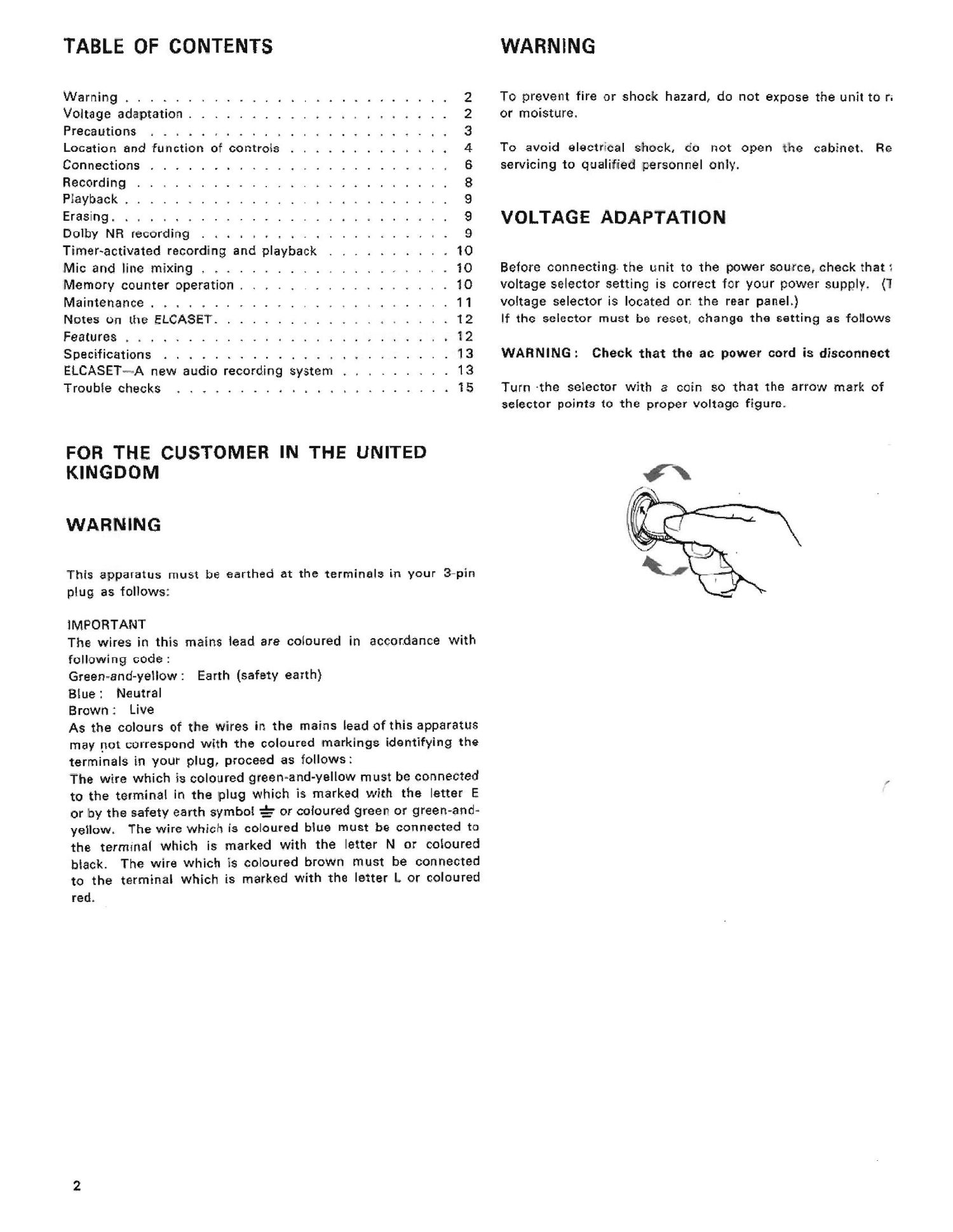
Before connecting. the unit to the power source? check that:
voltage selector setting is correct for your power supply! (1
voltage selector is located or. the rear panel.)

If the selector must be reset change the setting as foilowe
WARNING: Check that the ac power- cord is disconnect

Turn the selector with a win so that the arrow merit of
selector points to the proper voltage figure.

Page 2

iPRECAUTiONS

On safety.

lBefore operating. be sure the operating voltage of your unit
is identical with that of your local power supply.

QShould any liquid or solid ohieet fall into the cabinet. unplug
the unit and have it checked by qualified personnel before
operating it any further.

OUnplug the unit from the wall outlet if it is not to he used
for an extended period of time. To disconnect the cord. pull
it out by the plug. Never pull the cord itself.

On installation

lGood air circulation is essential to prevent internal heat
buildup in the unit. Place the unit in a location with adequate
air circuiation.

IDo not install the unit in a location near heat sources such
as radiators. or air duets, or in a place subject to direct sun-
light. excessive dust or mechanicai vibration.

iThe tape deck is designed for vertical operation oniv.

On head cleaning

7'? best performance of your tape deelk depends on your
putodic cleaning of the heads and all surfaces over which the
tape travels. Dirty heads and tape path cause:

- Less of high frequency response

.- Loss of sound volume

- Sound drop-tout. etc.

Cleaning should be done even,r after 10 hours of operation.
For detaiis. see MAINTENANCE" on page 11.

Playback waveform at 10 kHz

3%,: clean head

By dirty head
The output [svel fluctuates.

«fl-x
C" ' ifiill
. DWW head
u l l l
- -'l5 , l l l l . . . . I I II 11
E IEven hardly,r warble dust latter of N.
E 1 . 1.5a deteriorates "frequency response.
4,- :10 . . l I 7 i 7 l
=5 . .
G. l r
I _15" l 1
too 1k ' lDl-t

Frequency {Hz}

On ELCASET
lBefore inserting the ELCASET, take up the slack of the tape
to prevent it from becoming entangled around. the capstan.


- upplied tape driver

IHoId the ELCASET as illustrated and face its tape surface up
when inserting it in the tape deck. Avoid touching the tape
surface or pulling it out of the tape housing.

For more information on the ELCASET, see pages 12 and 13.

Dther important points to remember

IBefore depressing the PQWER switch. check to see that the
TIMEE switch is set at OFF. This switch should be placed to
REC or FLA? for timer-activated operation.

iREc oFF ate:

1-

IlllEentIyr close the hd of the ELGASET holder to its locked
position to protect the tape from damage.

aThe EJECT button is not depressed while tape is running.
lTurn down the REC LEVEL controls {MIC or LINE) not in use
while recording. '