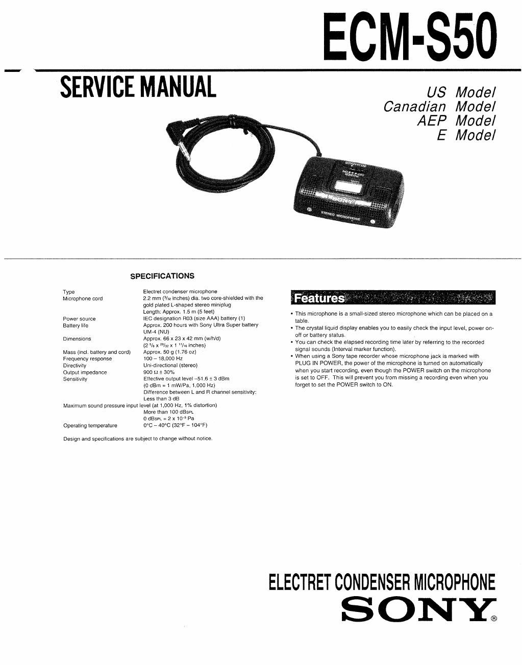
Sony ecm s 50 service manual

This is the 7 pages manual for sony ecm s 50 service manual.
Read or download the pdf for free. If you want to contribute, please mail your pdfs to info@audioservicemanuals.com.

Page: 1 / 7
left right
sony ecm s 50 service manual

Extracted text from sony ecm s 50 service manual (Ocr-read)


Page 1

ECM-SSO

SERVICE MANUAL us Model

Canadian Model
AEP Model
E Model

SPECIFICATIONS
Type Eleclrel condenser microphone
Microphone cord 22 mm (/32 inches) dia. 1W0 coreshielded with me

gold plaled L-shaped stereo miniplug
Length: Approx 1 5 m (5 leei)

. This microphone is a small-sized stereo microphone which can be placed on a

Power source IEC designahon R03 (SIZE AAA) baiiery (1) table
. h ' I .
Emery me GKENET OMS wnn Sony Uhra suPer bat ery ' The crystal liqwd display enables you to easily Check the input level, power on-
Drmensions Approx. ea x 23 x 42 mm (w/h/d) ° °' new satusi , ,
(2 5/5 X 29/32 X 1 "/16 inches) ~ You can check the elapsed recording time later by referring to the recorded
Mass (incl. ballery and cord) Approx 50 9 (L76 oz) 59" 509" (meva' marker UVCIWI
Frequency response 100 - 18,000 Hz - When usmg a Sony tape recorder whose microphone jack is marked wrih
Direcfivny Unhdiyecfiona] (siereo) PLUG IN POWER, me power of ihe microphone is turned on automatically
Oquul impedance 900 g) g 30% when you start recording, even ihough the POWER switch on the microphone
sensmvny Elleclive oulpul level 415 g 3 dam is set to OFF. This will prevent you from missing a recording even when you
(1) dBm = 1 mW/Pa, 1.000 H2) Iorgel to set the POWER swhch to ON

Drilerence beiween L and R channel sensmvify:
Less ihan 3 dB
Maxrmum sound pressure rnpui level (at 1,000 Hz, 1% dislonion)
More man 100 dBSPL
o dBSPL = 2 x10" Pa
Operating Iempelalure 0°C , 40%: (32F - 104%

Design and specmcalions are subjeci to change Wilhoul nolice.

ELECTRET CONDENSER MICROPHONE
S 0 NY;

Page 2

SECTION 1 This section is extracted from
GENERAL instruction manual.

to the microphone jack

Parts Identification and How to
se (Seetg I)

E} Lett channel microphone
E} Battery compartment
POWER/INT. MARKER (power/interval marker) switch

@

POWER OFF ON ON
INT. MARKER OFF OFF ON

Interval maker tunction

When the WT. MARKER switch is set to ON, the signal sound Peep" will be
recorded every 30 seconds. and the signal sound Peep peep" will be recorded
every 5 minutes. These sounds will be helpful when searching for the desired
portion later in the cue or review mode 01 the tape recorder (fast forward or
rewind in the playback mode).

When you do not want the signal sound In playback, set the POWER/INT.
MARKER switch to the center position when you start recording.

When the INT. MARKER switch is set to ON, the ON" indication appears on the
display.

Do not change the setting 0! the INT. MARKER switch during recording.
Automatic power-on system

When you use a Sony tape recorder whose microphone jack is marked with
PLUG lN POWER. such as the WM-DGC or TCS-ASO. etc.. the battery in the
microphone will activate when you start recording, even though the POWER
swttch on the microphone is set to OFF. In this case. the OPR (operation)
Indication appears on the display.

The INT. MARKER will not activate automatically

Liquid crystal display

[3 Recording level indicator

The indicator shows the Input level In three stages. When the sound level is
appropriate. the left and center Indicators will stay lit and the indicator on the
right sometimes llash. Decide on the position oi the microphone by relerring
to the indicator.

Right channel microphone

Output plug (Gold plated L-shaped stereo miniplug)

Connect this plug to the microphone jack oi a tape recorder.

HE}