Sony ecm 9030 service manual

This is the 4 pages manual for sony ecm 9030 service manual.
Read or download the pdf for free. If you want to contribute, please mail your pdfs to info@audioservicemanuals.com.

Page: 1 / 4
left right
sony ecm 9030 service manual

Extracted text from sony ecm 9030 service manual (Ocr-read)


Page 1

[CM-9030/9031

SERVICE MANUAL

for DR-6010/DR-6020
Microphone Amplifier
Note: The amplifier board in this set is replaced with a whole block
50 dont repair in the boards
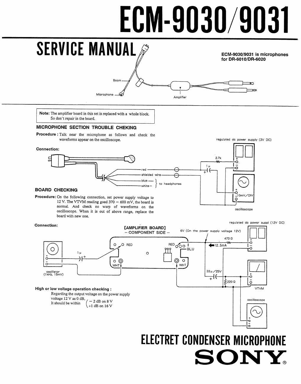
MICROPHONE SECTION TROUBLE CHEKING
Procedure : Talk near the microphone as follows and check the
waveforms appear on the oscilloscope. gum d° W3 3WD (3" Dc)
Connectlon: D I]
{\H 27" *
-M--0.
l u 0'
red A 1'} I-.-
shielded wire-._e_.__
blue- Q
whim- to headphones
BOARD CHECKING *

-O
, . .10mv/Dlv
Procedure: On the followmg connection, set power supply voltage to L
12 V. The VTVM reading goed 370 - 600 mV, the board is j)
normal. And check no warp of waveforms on the
oscilloscope. When it is out of above range, replace the
board with new one.

oscilloscope

regulased dc power SUDDI (12V DC)

9333;535:3273; _ o (On m, j l:
t

470 Q

o 0 RED REDOOO l (-12.5mA [-
BLU -8
n o [Til]
+

0 © © 0
o---\ WHT wm /
as later 33u/25V
(lkHZ, 15mV)

Connection:

e
+ K 2
ézzo :2 L9
High or low voltage operation checking : VTVM
Regarding the oulput voltage on the power supply
voltage 12 V as 0 dB, oscilloscope
. . - 2 dB on 8 V
ll should be Within (+1 dB on 16 V
+ :
l
' l_._°

ELECTRET CONDENSER MICROPHONE
S ONY;

Page 2

Note: The amplifier board in this set is replaced with a whole block.
So dont repair in the board.
The schematic diagram on this page is for reference.

WIRING DIAGRAM

[AMPLIFIER BOARD]
(COMPONENT SIDE)

T0 RECEIVER 9% RI


RECEIVER PLUG
PJ U
MICROPHONE

ASSY

RECEIVEE
momma/7020 C

_ WHT
SHIELDED WIRE

' MICROPHONE PLUG
SHIELDED WIRE PJ-OBBU
To MICROPHONE

SCHEMATIC DIAGRAM I- ECMeoaI h}
I I
I geceivsr PlugzPJ-OSSU i
L. ___________ _I
J1
l .04- °

r-_-EEII7$EJ-i
.
|
I

I
P1 1
Receiver Plug : PJ-055U

Receiver Connector _ i_ _ _ _ _ .4
X R1 R2 R5 R9
I .5k 470 1 k 56
,u. .u wv Re I.
5.3K , p2

R3 .,
--- ask:-
r- -I a
c2 02
I 2200P m fl)
I
I g Q) 4.7192331 V082" Microphone PlugzPJrOeeu
ca i --)I- R7
: 4.7 II /6.3 A " 5c: 330k 377
' ' II
L.__.._._J VDF t- .. +6.3
= " A _, R4 Fla 1» :;
Microphone Capsule c4 DI < 82 53 - .
.om HZSAI
regulated cc
OI 2280245BBL 0252807744
- AUDIO AMP.-

: Note on Replacing Microphone Assy and Amplifier Board.

0 When replacing microphone assy, replace R1 on the
amplifier board with 2.7 kg resistor.

O Amplifier board replacing.
27 k9 resistor is mounted as R1 on the amplifier board
for replacement.
So replace R1 on new one with the same value resistor as
it on the broken board.