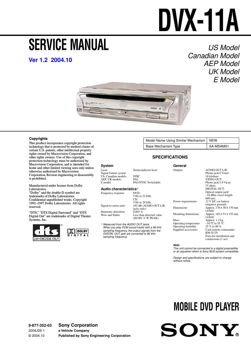
Sony dvx 11 a service manual

This is the 56 pages manual for sony dvx 11 a service manual.
Read or download the pdf for free. If you want to contribute, please mail your pdfs to info@audioservicemanuals.com.

Page: 1 / 56
left right
sony dvx 11 a service manual

Extracted text from sony dvx 11 a service manual (Ocr-read)


Page 2

3 DVX-11A TABLE OF CONTENTS 1. SERVICING NOTES ................................................ 4 2. GENERAL Location of Controls ....................................................... 7 3. DISASSEMBLY 3-1. Disassembly Flow........................................................... 11 3-2. Cove r........................................................................\ ....... 12 3-3. Front P anel Assy............................................................. 12 3-4. Mechanism Deck (SA-MDAM01)................................. 13 3-5. DSP Board, MAIN Board............................................... 13 3-6. Brack et L/R..................................................................... 14 3-7. Chassis (DVD) Block...................................................... 14 3-8. SERVO Board................................................................. 15 3-9. Gear Cove r...................................................................... 15 3-10. Feed Motor (Loading) (M1)........................................... 16 3-11. Chassis Clamp ................................................................. 16 3-12. Brack et Roller................................................................. 17 4. ELECTRICAL ADJUSTMENTS ......................... 17 5. DIAGRAMS 5-1. Block Diagram ................................................................ 18 5-2. Note for Printed Wiring Boards and Schematic Diagrams ....................................................... 19 5-3. Printed Wiring Boards -“ MAIN Section (1/2) -“........... 20 5-4. Printed Wiring Boards -“ MAIN Section (2/2) -“........... 21 5-5. Schematic Diagram -“ MAIN Section (1/2) -“................ 22 5-6. Schematic Diagram -“ MAIN Section (2/2) -“................ 23 5-7. Printed Wiring Board -“ KEY Board -“........................... 24 5-8. Schematic Diagram -“ KEY Board -“............................. 25 5-9. IC Pin Function Description........................................... 27 6. EXPLODED VIEWS 6-1. Overall Section................................................................ 29 6-2. Front P anel Section......................................................... 30 6-3. Chassis Section ............................................................... 31 6-4. Mechanism Deck Section-1 (SA-MDAM01) ................. 32 6-5. Mechanism Deck Section-2 (SA-MDAM01) ................. 33 7. ELECTRICAL PARTS LIST ............................... 34