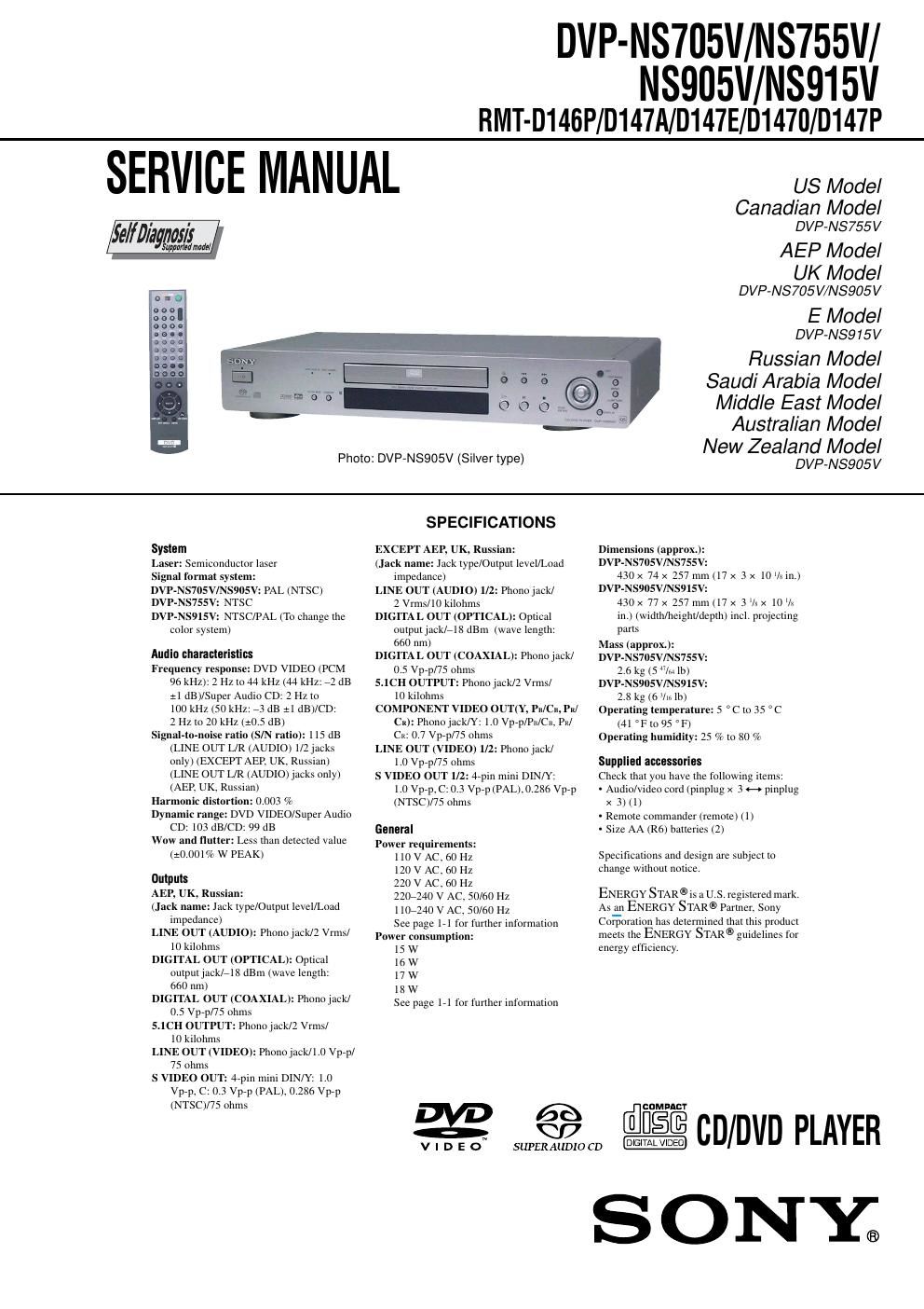
Sony dvpns 705 v service manual

This is the 125 pages manual for sony dvpns 705 v service manual.
Read or download the pdf for free. If you want to contribute, please mail your pdfs to info@audioservicemanuals.com.

Page: 1 / 125
left right
sony dvpns 705 v service manual

Extracted text from sony dvpns 705 v service manual (Ocr-read)


Page 2

-“ 3 -“ T ABLE OF CONTENTS Section Title Page Section Title Page Service Note ........................................................................\ .... 4 1. GENERAL Precautions................................................................... 1-1 Simple Start Guide........................................................ 1-3 Hookups ........................................................................\ 1-4 Playing Discs ................................................................. 1-8 Searching for a Scene................................................... 1-11 Viewing Information About the Disc.............................. 1-12 Sound Adjustments ....................................................... 1-13 Enjoying Mo vies............................................................ 1-14 Using Various Additional Functions ..............................1-16 Settings and Adjustments ............................................. 1-18 Additional Infor mation................................................... 1-20 2. DISASSEMBLY 2-1. Case Removal............................................................... 2-1 2-2. Tray Cover Assy Removal ............................................ 2-1 2-3. Front Panel Block Assy Removal ................................. 2-1 2-4. Power Block Removal ................................................... 2-1 2-5. Mechanism Deck Removal ........................................... 2-2 2-6. AV-64 Board Removal ................................................... 2-2 2-7. MB-105 Board Removal ................................................ 2-2 2-8. ER-19 Board Removal .................................................. 2-2 2-9. IF-94 Board Removal .................................................... 2-3 2-10. Optical Pick-up Remo val............................................... 2-3 2-11. Internal Vie ws ................................................................ 2-4 2-12. Circuit Boards Location................................................. 2-5 3. BLOCK DIAGRAMS 3-1. Overall Block Diagram................................................... 3-1 3-2. RF/Servo Block Diagram............................................... 3-3 3-3. Signal Processor Block Diagram.................................. 3-5 3-4. System Control Block Diagram..................................... 3-7 3-5. Video (1) Block Diagram ............................................... 3-9 3-6. Video (2) Block Diagram ...............................................3-11 3-7. Audio (1) Block Diagram ...............................................3-13 3-8. Audio (2) Block Diagram ...............................................3-15 3-9. Interface Control Block Diagram ...................................3-17 3-10. Power (1) Bloc k Diagram.............................................. 3-19 3-11. Power (2) Bloc k Diagram.............................................. 3-21 4. PRINTED WIRING BOARDS AND SCHEMATIC DIAGRAMS 4-1. Frame Schematic Diag ram ............................................ 4-3 4-2. Printed Wiring Boards and Schematic Diagrams......... 4-5 MS-81 (LOADING) Printed Wiring Board and Schematic Diagra m................................................ 4-5 MB-105 Printed Wir ing Board....................................... 4-7 MB-105 (RF AMP, SERVO) Schematic Diagram.......... 4-11 MB-105 (ARP, SERVO DSP) Schematic Diagram........ 4-13 MB-105 (AV DECODER) Schematic Diagram.............. 4-15 MB-105 (MOTOR DRIVE) Schematic Diagram............4-17 MB-105 (SYSTEM CONTROL) Schematic Diagra m....................................................... 4-19 MB-105 (CLOCK GENERATOR) Schematic Diagra m....................................................... 4-21 MB-105 (I/P CONVERTOR) Schematic Diagram.........4-23 MB-105 (VIDEO ENCODER, AUDIO D/A CONVERTER) Schematic Diag ram .............................. 4-25 MB-105 (AUDIO DSP) Schematic Diagram.................. 4-27 MB-105 (2ch/6ch DAC) Schematic Diagram................ 4-29 MB-105 (SACD DECODER) Schematic Diagram........4-31 LE-34 (LED) Printed Wiring Board and Schematic Diagra m................................................ 4-33 AV -64 Printed Wir ing Board.......................................... 4-35 AV -64 (VIDEO BUFFER) Schematic Diagram.............. 4-39 AV -64 (AUDIO AMP) Schematic Diagram.................... 4-41 AV -64 (5.1CH AUDIO AMP) Schematic Diagram.........4-43 IF-94 Printed Wir ing Board........................................... 4-45 IF-94 (IF CON) Schematic Diag ram ............................. 4-49 ER-19 Printed Wir ing Board.......................................... 4-51 ER-19 (EURO AV) Schematic Diagram........................ 4-53 ETXNY393N2F Printed Wir ing Board........................... 4-55 ETXNY393N2F (SWITCHING REGULATOR) Schematic Diagra m....................................................... 4-57 HS12S1U Printed Wir ing Board.................................... 4-59 HS12S1U Schematic Diagra m...................................... 4-61 HS12S1F Printed Wir ing Board.................................... 4-63 HS12S1F Schematic Diagra m...................................... 4-65 5. IC PIN FUNCTION DESCRIPTION 5-1. System Control Pin Function (MB-105 Board IC104) .................................................. 5-1 6.TEST MODE 6-1. General Descr iption...................................................... 6-1 6-2. Starting T est Mode........................................................ 6-1 6-3. Syscon Diagnosis .......................................................... 6-1 6-4. Drive Auto Adjustment .................................................. 6-6 6-5. Drive Manual Operation ................................................ 6-8 6-6. Mecha Aging ................................................................. 6-11 6-7. Emergency History ........................................................ 6-11 6-8. Version Information ....................................................... 6-12 6-9. Video Level Adjustment ................................................6-12 6-10. IF CON Self Diagnostic Function .................................. 6-12 6-11. Troub leshooting............................................................. 6-19 7. ELECTRICAL ADJUSTMENT 7-1. Power Supply Check..................................................... 7-1 1. ETXNY393N2F/HS12S1U/HS12S1F ...........................7-1 7-2. Adjustment of Video System......................................... 7-2 1. Video Lev el Adjustment................................................ 7-2 2. Progressive Video Output Level Adjustment ................7-2 3. Checking S Video Output S-Y....................................... 7-2 4. Checking S Video Output S-C....................................... 7-2 5. Checking Component Video Output Y.......................... 7-3 6. Checking Component Video Output B-Y...................... 7-3 7. Checking Component Video Output R-Y...................... 7-3 7-3. Adjustment Related Parts Arrangement ....................... 7-6 8. REPAIR PARTS LIST 8-1. Exploded Views ............................................................. 8-1 8-1-1. Front Panel Assembly (NS705V/NS755V) ..............8-1 8-1-2. Front Panel Assembly (NS905V/NS915V) ..............8-2 8-1-3. Chassis Assembly (NS705V/NS755V)....................8-3 8-1-4. Chassis Assembly (NS905V/NS915V)....................8-4 8-1-5. Mechanism Deck Assembly..................................... 8-5 8-2. Electrical Parts List ....................................................... 8-6