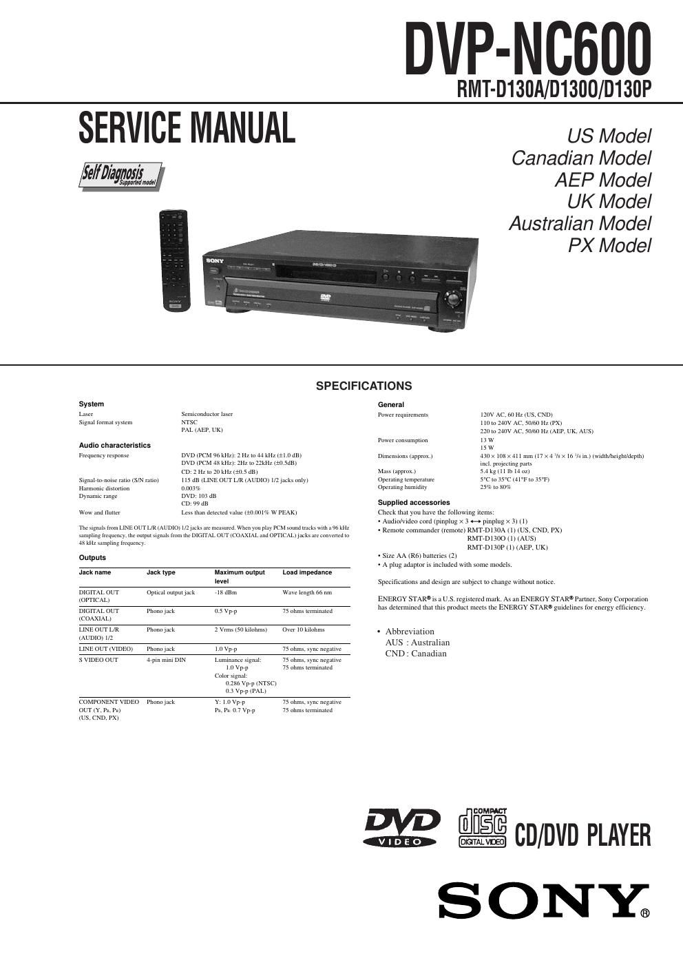
Sony dvpnc 600 service manual

This is the 115 pages manual for sony dvpnc 600 service manual.
Read or download the pdf for free. If you want to contribute, please mail your pdfs to info@audioservicemanuals.com.

Page: 1 / 115
left right
sony dvpnc 600 service manual

Extracted text from sony dvpnc 600 service manual (Ocr-read)


Page 2

-“ 3 -“ TABLE OF CONTENTS Section Title Page Section Title Page Service Note ............................................................................ 4 1. GENERAL Index to Parts and Controls .......................................... 1-1 Getting Started .............................................................. 1-3 Hookups ........................................................................ 1-3 Playing Discs ................................................................. 1-7 Searching for a Scene ................................................... 1-10 Viewing Information About the Disc .............................. 1-10 Sound Adjustments ....................................................... 1-11 Enjoying Movies ............................................................ 1-12 Using Various Additional Functions .............................. 1-12 Settings and Adjustments ............................................. 1-14 Additional Information ................................................... 1-16 2. DISASSEMBLY 2-1. Upper Case, Reinforcement (C) Removal.................... 2-1 2-2. Front Panel Section Removal ........................................ 2-1 2-3. Rear Panel Removal ..................................................... 2-1 2-4. MB-98 Board Removal .................................................. 2-1 2-5. AV-57 Board Removal ................................................... 2-2 2-6. ER-16 Board Removal (AEP, UK) ................................. 2-2 2-7. Table Assy Removal ..................................................... 2-2 2-8. Chassis Assy ................................................................ 2-2 2-9. CN-142 Board Removal ................................................ 2-3 2-10. Loading Motor Assy (M851) Removal .......................... 2-3 2-11. BU Holder Assy Removal ............................................. 2-3 2-12. Optical Pick-up Removal ............................................... 2-3 2-13. Power Block Removal ................................................... 2-4 2-14. Internal Views ................................................................ 2-5 2-15. Circuit Boards Location ................................................. 2-6 3. BLOCK DIAGRAMS 3-1. Overall Block Diagram ................................................... 3-1 3-2. RF/Servo Block Diagram ............................................... 3-3 3-3. Signal Processor Block Diagram .................................. 3-5 3-4. System Control Block Diagram ..................................... 3-7 3-5. Video Block Diagram ..................................................... 3-9 3-6. Audio Block Diagram ..................................................... 3-11 3-7. Interface Control Block Diagram ................................... 3-13 3-8. Power 1 Block Diagram ................................................. 3-15 3-9. Power 2 Block Diagram ................................................. 3-17 4. PRINTED WIRING BOARDS AND SCHEMATIC DIAGRAMS 4-1. Frame Schematic Diagram ............................................ 4-3 4-2. Printed Wiring Boards and Schematic Diagrams ......... 4-7 MB-98 Printed Wiring Board ......................................... 4-7 MB-98 (RF AMP, SERVO) Schematic Diagram ............ 4-11 MB-98 (ARP, SERVO DSP) Schematic Diagram .......... 4-13 MB-98 (AV DECODER) Schematic Diagram ................ 4-15 MB-98 (BNR) Schematic Diagram ................................ 4-17 MB-98 (DRIVE) Schematic Diagram ............................ 4-19 MB-98 (SYSTEM CONTROL) Schematic Diagram ....................................................... 4-21 MB-98 (CLOCK GENERATOR) Schematic Diagram ....................................................... 4-23 MB-98 (AUDIO DSP, D/A CONVERTER) Schematic Diagram ....................................................... 4-25 AV-57 Printed Wiring Board .......................................... 4-29 AV-57 (VIDEO BUFFER) Schematic Diagram .............. 4-31 AV-57 (AUDIO AMP) Schematic Diagram .................... 4-33 ER-16 Printed Wiring Board (AEP, UK) ........................ 4-35 ER-16 Schematic Diagram (AEP, UK) .......................... 4-37 IF-81 Printed Wiring Board ........................................... 4-39 IF-81 Schematic Diagram ............................................. 4-41FL-119, FR-178, SW-353 Printed Wiring Boards ......... 4-43 FL-119 (FUNCTION SWITCH), FR-178 (FUNCTION SWITCH), SW-353 (FUNCTION SWITCH) Schematic Diagram ... 4-45 CN-142, LM-63 Printed Wiring Board ........................... 4-47 CN-142 (CONNECTION), LM-63 (LOADING MOTOR) Schematic Diagram ....................................................... 4-49 SE-122, TM-125 Printed Wiring Board ......................... 4-51 SE-122 (SENSOR), TM-125 (TURNTABLE MOTOR) Schematic Diagram ....................................................... 4-53 MPN4801 Printed Wiring Board (US, CND) ................. 4-55 MPN4801 Schematic Diagram (US, CND) ................... 4-57 MPN4901 Printed Wiring Board (AEP, UK, AUS, PX) .. 4-59 MPN4901 Schematic Diagram (AEP, UK, AUS, PX) .... 4-61 5. IC PIN FUNCTION DESCRIPTION 5-1. System Control Pin Function (MB-98 Board IC103) .................................................... 5-1 6. TEST MODE 6-1. General Description ...................................................... 6-1 6-2. Starting Test Mode ........................................................ 6-1 6-3. Syscon Diagnosis .......................................................... 6-1 6-4. Drive Auto Adjustment .................................................. 6-5 6-5. Drive Manual Operation ................................................ 6-7 6-6. Mecha Aging ................................................................. 6-10 6-7. Emergency History ........................................................ 6-10 6-8. Version Information ....................................................... 6-11 6-9. Video Level Adjustment ................................................ 6-11 6-10. IF CON Self Diagnostic Function .................................. 6-11 6-11. Troubleshooting ............................................................. 6-18 7. ELECTRICAL ADJUSTMENT 7-1. Power Supply Check ..................................................... 7-1 1. MPN4801/MPN4901 Boards ......................................... 7-1 2. +11 V Adjustment .......................................................... 7-1 3. +5 V Adjustment ............................................................ 7-1 4. -“11 V Adjustment .......................................................... 7-1 7-2. Adjustment of Video System ......................................... 7-2 1. Video Level Adjustment (MB-98 Board) ....................... 7-2 2. Checking S Video Output S-Y ....................................... 7-2 3. Checking S Video Output S-C ....................................... 7-2 4. Checking Component Video Output Y .......................... 7-2 5. Checking Component Video Output B-Y ...................... 7-3 6. Checking Component Video Output R-Y ...................... 7-3 7. Checking RGB Output R ............................................... 7-3 8. Checking RGB Output G ............................................... 7-3 9. Checking RGB Output B ............................................... 7-4 7-3. Adjustment Related Par ts Arrangement ....................... 7-6 8. REPAIR PARTS LIST 8-1. Exploded Views ............................................................. 8-1 8-1-1. Main Assembly ......................................................... 8-1 8-1-2. Front Panel Assembly .............................................. 8-3 8-1-3. Table Assembly ........................................................ 8-4 8-1-4. Chassis Assembly .................................................... 8-5 8-2. Electrical Parts List ....................................................... 8-6 - Abbreviation AUS : Australian CND : Canadian