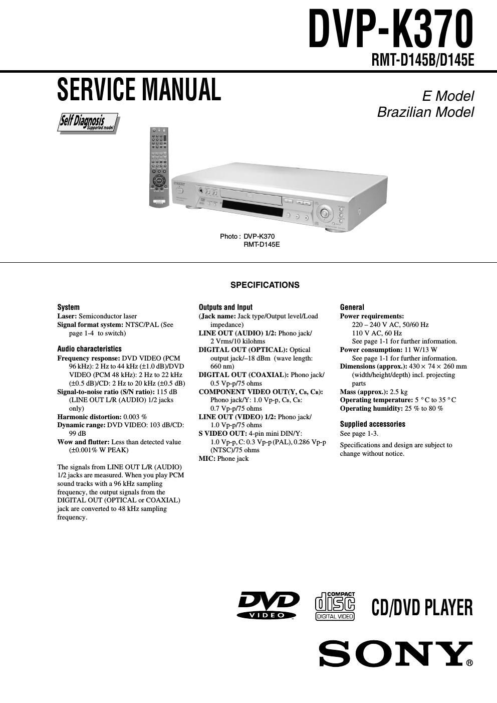
Sony dvpk 370 service manual

This is the 106 pages manual for sony dvpk 370 service manual.
Read or download the pdf for free. If you want to contribute, please mail your pdfs to info@audioservicemanuals.com.

Page: 1 / 106
left right
sony dvpk 370 service manual

Extracted text from sony dvpk 370 service manual (Ocr-read)


Page 1

- 2 - SAFETY-RELATED COMPONENT WARNING!! COMPONENTS IDENTIFIED BY MARK 0 OR DOTTED LINE WITH MARK 0 ON THE SCHEMATIC DIAGRAMS AND IN THE PARTS LIST ARE CRITICAL TO SAFE OPERATION. REPLACE THESE COMPONENTS WITH SONY PARTS WHOSE PART NUMBERS APPEAR AS SHOWN IN THIS MANUAL OR IN SUPPLEMENTS PUBLISHED BY SONY. 1. Check the area of your repair for unsoldered or poorly-soldered connections. Check the entire board surface for solder splashes and bridges. 2. Check the interboard wiring to ensure that no wires are "pinched" or contact high-wattage resistors. 3. Look for unauthorized replacement parts, particularly transistors, that were installed during a previous repair. Point them out to the customer and recommend their replacement.4. Look for parts which, through functioning, show obvious signs of deterioration. Point them out to the customer and recommend their replacement. 5. Check the B+ voltage to see it is at the values specified. 6. Flexible Circuit Board Repairing -Keep the temperature of the soldering iron around 270˚C during repairing. -Do not touch the soldering iron on the same conductor of the circuit board (within 3 times). -Be careful not to apply force on the conductor when soldering or unsoldering. SAFETY CHECK-OUT After correcting the original service problem, perform the following safety checks before releasing the set to the customer. CAUTION Use of controls or adjustments or performance of procedures other than those specified herein may result in hazardous radiation exposure. WARNING!! WHEN SERVICING, DO NOT APPROACH THE LASER EXIT WITH THE EYE TOO CLOSELY. IN CASE IT IS NECESSARY TO CONFIRM LASER BEAM EMISSION, BE SURE TO OBSERVE FROM A DISTANCE OF MORE THAN 25 cm FROM THE SURFACE OF THE OBJECTIVE LENS ON THE OPTICAL PICK-UP BLOCK. CAUTION: The use of optical instrument with this product will increase eye hazard. Unleaded solder Boards requiring use of unleaded solder are printed with the lead- free mark (LF) indicating the solder contains no lead. (Caution: Some printed circuit boards may not come printed with the lead free mark due to their particular size.) : LEAD FREE MARK Unleaded solder has the following characteristics. -Unleaded solder melts at a temperature about 40°C higher than ordinary solder. Ordinary soldering irons can be used but the iron tip has to be applied to the solder joint for a slightly longer time. Soldering irons using a temperature regulator should be set to about 350°C. Caution: The printed pattern (copper foil) may peel away if the heated tip is applied for too long, so be careful! -Strong viscosity Unleaded solder is more viscous (sticky, less prone to flow) than ordinary solder so use caution not to let solder bridges occur such as on IC pins, etc. -Usable with ordinary solder It is best to use only unleaded solder but unleaded solder may also be added to ordinary solder.

Page 2

- 3 - TABLE OF CONTENTS SERVICE NOTE 1. DISC REMOVAL PROCEDURE (at POWER OFF)········5 2. HOW TO SERVICE MB-103 BOARD······························5 3. CONNECTION OF SERVICE JIG····································7 1. GENERAL WARNING············································································1-1 Welcome!···············································································1-1 Precautions·············································································1-1 About this Manual·································································1-1 This Player Can Play the Following Discs····························1-1 Notes about the Discs····························································1-1 Index to Parts and Controls····················································1-2 Guide to the Control Menu Display·······································1-3 Simple Start Guide····································································1-3 Quick Overview·····································································1-3 Step 1: Unpacking·································································1-3 Step 2: Inserting Batteries into the Remote···························1-3 Step 3: TV Hookups······························································1-4 Step 4: Playing a Disc····························································1-4 Hookups·····················································································1-4 Hooking Up the Player··························································1-4 Step 1: Connecting the Video Cords······································1-4 Step 2: Connecting the Audio Cords·····································1-5 Step 3: Connecting the Power Cord·······································1-6 Step 4: Quick Setup·······························································1-6 Playing Discs·············································································1-7 Playing Discs·········································································1-7 Searching for a Particular Point on a Disc (Search, Scan, Slow-motion Play, Freeze Frame)··············1-7 Resuming Playback from the Point Where You Stopped the Disc (Multi-disc Resume)···················································1-7 Using the DVDs Menu·························································1-8 Playing VIDEO CDs with PBC Functions (PBC Playback)·· 1-8 Playing an MP3 Audio Track·················································1-8 Various Play Mode Functions (Programme Play, Shuffle Play, Repeat Play, A-B Repeat Play)···········································1-8 Searching for a Scene······························································1-10 Searching for a Title/Chapter/Track/Index/Scene (Search mode)···································································1-10 Searching by Scene (PICTURE NAVIGATION)················1-10 Enjoying Karaoke····································································1-10 Using Karaoke·····································································1-10 Selecting the Vocals (Vocal Select)······································1-11 Viewing Information About the Disc·······································1-11 Checking the Playing Time and Remaining Time···············1-11 Checking the Play Information············································1-12 Sound Adjustments··································································1-12 Changing the Sound·····························································1-12 TV Virtual Surround Settings (TVS)···································1-12 Enjoying Movies·····································································1-13 Changing the Angles····························································1-13 Displaying the Subtitles·······················································1-13 Adjusting the Picture Quality (BNR)··································1-13 Adjusting the Playback Picture (CUSTOM PICTURE MODE)·· 1-13 Enhancing the Playback Picture (DIGITAL VIDEO ENHANCER)···································································1-14 Using Various Additional Functions········································1-14 Locking Discs (CUSTOM PARENTAL CONTROL, PARENTAL CONTROL)·················································1-14 Controlling Your TV or AV Amplifier (Receiver) with the Supplied Remote·······························································1-15 Settings and Adjustments························································1-16 Using the Setup Display······················································1-16 Setting the Display or Sound Track Language (LANGUAGE SETUP)····················································1-16 Settings for the Display (SCREEN SETUP)·······················1-16Custom Settings (CUSTOM SETUP)·································1-16 Settings for the Sound (AUDIO SETUP)····························1-17 Additional Information····························································1-17 Troubleshooting···································································1-17 Self-diagnosis Function (When letters/numbers appear in the display)·············································································1-18 Glossary···············································································1-18 Language Code List·····························································1-18 2. DISASSEMBLY 2-1. CASE, TRAY COVER ASSEMBLY······························2-2 2-2. FRONT PANEL ASSEMBLY·········································2-2 2-3. MECHANISM DECK·····················································2-3 2-4. OPTICAL PICK-UP (KHM-270AAA)···························2-3 2-5. DC-MOTOR, MS-81T BOARD·····································2-4 2-6. MB-103KM (GA) BOARD·············································2-4 2-7. AV-63KM (GA) BOARD················································2-5 2-8. POWER BLOCK·····························································2-5 2-9. IF-092KM (GA) BOARD···············································2-6 2-10. MC-139 BOARD·····························································2-6 2-11. INTERNAL VIEWS························································2-7 2-12. CIRCUIT BOARDS LOCATION···································2-8 3. BLOCK DIAGRAMS 3-1. OVERALL BLOCK DIAGRAM····································3-1 3-2. RF/SERVO BLOCK DIAGRAM····································3-3 3-3. SIGNAL PROCESSOR BLOCK DIAGRAM················3-5 3-4. SYSTEM CONTROL BLOCK DIAGRAM···················3-7 3-5. VIDEO BLOCK DIAGRAM··········································3-9 3-6. AUDIO BLOCK DIAGRAM········································3-11 3-7. INTERFACE CONTROL BLOCK DIAGRAM···········3-13 3-8. POWER BLOCK DIAGRAM (1/3)······························3-15 3-9. POWER BLOCK DIAGRAM (2/3)······························3-17 3-10. POWER BLOCK DIAGRAM (3/3)······························3-19 4. PRINTED WIRING BOARDS AND SCHEMATIC DIAGRAMS 4-1. FRAME SCHEMATIC DIAGRAM································4-1 4-2. PRINTED WIRING BOARDS AND SCHEMATIC DIAGRAM······································································4-4 - MS-81 (LOADING) PRINTED WIRING BOARD AND SCHEMATIC DIAGRAM······························4-5 - MB-103 (DVD/CD RF AMP, DIGITAL SERVO, MOTOR DRIVE, SERVO, AV DECODER, SDRAM, SYSTEM CONTROL, AUDIO DAC, PLL) PRINTED WIRING BOARD·························4-7 - MB-103 (DVD/CD RF AMP, DIGITAL SERVO) (1/7) SCHEMATIC DIAGRAM····························4-11 - MB-103 (MOTOR DRIVE) (2/7) SCHEMATIC DIAGRAM····························4-13 - MB-103 (SERVO) (3/7) SCHEMATIC DIAGRAM····························4-15 - MB-103 (AV DECODER) (4/7) SCHEMATIC DIAGRAM····························4-17 - MB-103 (SDRAM) (5/7) SCHEMATIC DIAGRAM····························4-19 - MB-103 (SYSTEM CONTROL) (6/7) SCHEMATIC DIAGRAM····························4-21 - MB-103 (AUDIO DAC, PLL) (7/7) SCHEMATIC DIAGRAM····························4-23 - AV-063 (AUDIO OUT, VIDEO OUT) PRINTED WIRING BOARD·······················4-25 - AV-063 (AUDIO OUT) (1/2) SCHEMATIC DIAGRAM····························4-27 - AV-063 (VIDEO OUT) (2/2) SCHEMATIC DIAGRAM····························4-29