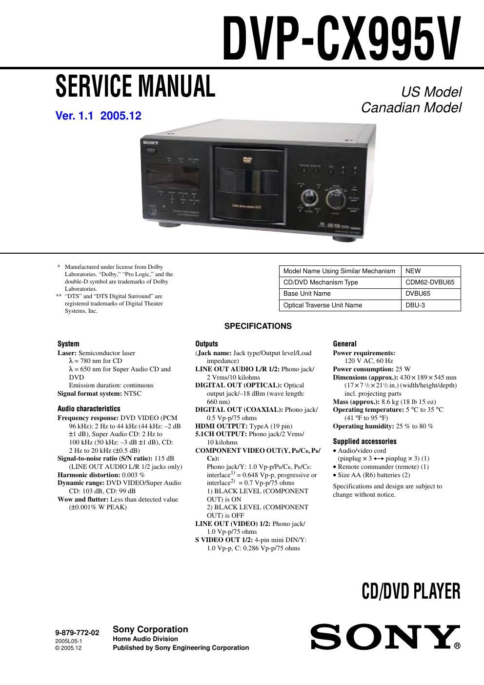
Sony dvpcx 995 v service manual

This is the 116 pages manual for sony dvpcx 995 v service manual.
Read or download the pdf for free. If you want to contribute, please mail your pdfs to info@audioservicemanuals.com.

Page: 1 / 116
left right
sony dvpcx 995 v service manual

Extracted text from sony dvpcx 995 v service manual (Ocr-read)


Page 2

3 DVP-CX995V TABLE OF CONTENTS 1. SERVICING NOTES ............................................... 4 2. GENERAL ................................................................... 9 3. DISASSEMBLY 3-1. Disassembly Flow ........................................................... 10 3-2. Case ................................................................................. 11 3-3. MB Board ........................................................................ 11 3-4. AV Board ......................................................................... 12 3-5. Bracket (L)/(R) ................................................................ 12 3-6. Front Panel Section ......................................................... 13 3-7. Cover (PT)/(CDM) .......................................................... 13 3-8. DVBU65 Assy ................................................................. 14 3-9. Switching Regulator ........................................................ 14 3-10. Table (400) Assy .............................................................. 15 3-11. Door Assy, Base (Door) Assy .......................................... 15 3-12. DC Motor (Door) (M603) ............................................... 16 3-13. Holder (Table Sensor 400) ............................................... 16 3-14. D. SENS OUT Board, D. SENS IN Board ...................... 17 3-15. Pop-up (400) Assy ........................................................... 17 3-16. DOOR SW Board ............................................................ 18 3-17. LOCK SW Board, LOADING SW Board ...................... 19 3-18. CD/DVD Mechanism Deck Block (CDM62-DVBU65) ......................................................... 20 3-19. Motor (400) Assy (Loading) (M602)/(Table) (M601), LOADING MOTOR Board ............................................. 20 3-20. Optical Traverse Unit (DBU-3) ....................................... 21 4. TEST MODE .............................................................. 22 5. MECHANICAL ADJUSTMENTS ....................... 32 6. ELECTRICAL ADJUSTMENTS ......................... 33 7. DIAGRAMS 7-1. Block Diagram -“ SERVO Section -“ ................................ 38 7-2. Block Diagram -“ AUDIO Section -“ ................................ 39 7-3. Block Diagram -“ VIDEO Section -“ ................................ 40 7-4. Block Diagram -“ PANEL, TABLE, POWER SUPPLY Section -“ ............ 41 7-5. Printed Wiring Board -“ RF TRANSLATION Board -“ ... 43 7-6. Printed Wiring Board -“ MB Board (Side A) -“ ................ 44 7-7. Printed Wiring Board -“ MB Board (Side B) -“ ................ 45 7-8. Schematic Diagram -“ MB Section (1/7) -“ ...................... 46 7-9. Schematic Diagram -“ MB Section (2/7) -“ ...................... 47 7-10. Schematic Diagram -“ MB Section (3/7) -“ ...................... 48 7-11. Schematic Diagram -“ MB Section (4/7) -“ ...................... 49 7-12. Schematic Diagram -“ MB Section (5/7) -“ ...................... 50 7-13. Schematic Diagram -“ MB Section (6/7) -“ ...................... 51 7-14. Schematic Diagram -“ MB Section (7/7) -“ ...................... 52 7-15. Schematic Diagram -“ AV Board (1/5) -“ .......................... 53 7-16. Schematic Diagram -“ AV Board (2/5) -“ .......................... 54 7-17. Schematic Diagram -“ AV Board (3/5) -“ .......................... 55 7-18. Schematic Diagram -“ AV Board (4/5) -“ .......................... 56 7-19. Schematic Diagram -“ AV Board (5/5) -“ .......................... 57 7-20. Printed Wiring Board -“ AV Board (Component Side) -“ ..................................... 58 7-21. Printed Wiring Board -“ AV Board (Conductor Side) -“ ....................................... 59 7-22. Printed Wiring Boards -“ TABLE Section -“ ..................... 60 7-23. Schematic Diagram -“ TABLE Section -“ ......................... 61 7-24. Printed Wiring Board -“ DRIVER Board -“ ...................... 62 7-25. Schematic Diagram -“ DRIVER Board -“ ......................... 63 7-26. Printed Wiring Board -“ PANEL-L Board -“ ..................... 64 7-27. Schematic Diagram -“ PANEL-L Board -“ ....................... 657-28. Printed Wiring Boards -“ PANEL-R Section -“ ................. 66 7-29. Schematic Diagram -“ PANEL-R Section -“ ..................... 67 8. EXPLODED VIEWS 8-1. Overall Section ................................................................ 90 8-2. Front Panel Section ......................................................... 91 8-3. Power Block Section ....................................................... 92 8-4. Table Section ................................................................... 93 8-5. Chassis Section ................................................................ 94 8-6. Base (Door) Section ........................................................ 95 8-7. CD/DVD Mechanism Deck Section-1 (Pop-up Block) ................................................................ 96 8-8. CD/DVD Mechanism Deck Section-2 (Pulley Block) .................................................................. 97 8-9. CD/DVD Mechanism Deck Section-3 (Lever, Holder Block) ...................................................... 98 8-10. CD/DVD Mechanism Deck Section-4 (Gear, Motor Block) ........................................................ 99 8-11. Base Unit Section (DVBU65) ........................................ 100 9. ELECTRICAL PARTS LIST ............................... 101