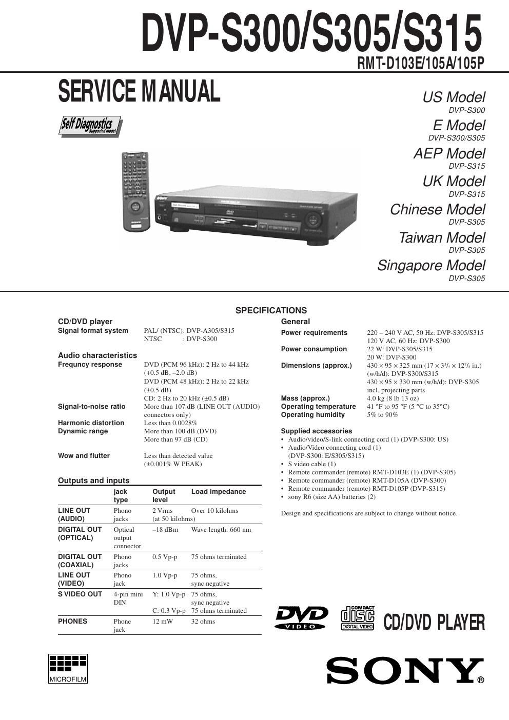
Sony dvp s300

This is the 75 pages manual for sony dvp s300.
Read or download the pdf for free. If you want to contribute, please mail your pdfs to info@audioservicemanuals.com.

Page: 1 / 75
left right
sony dvp s300

Extracted text from sony dvp s300 (Ocr-read)


Page 2

Ð 3 Ð TABLE OF CONTENTS Section Title Page Section Title Page Service Note ............................................................................ 4 1. GENERAL This Player Can Play the Following Discs .................... 1-1 Getting Started .............................................................. 1-1 Basic Operations ........................................................... 1-2 Playing Discs in Various Modes .................................... 1-4 Setting and Adjustments ............................................... 1-8 Additional Information ................................................... 1-9 2. DISASSEMBLY 2-1. Case Removal ............................................................... 2-1 2-2. Front Panel Section Removal....................................... 2-1 2-3. MB-78 Board Removal .................................................. 2-1 2-4. AU-197 Board Removal ................................................ 2-1 2-5. MD Block AssÕy Removal .............................................. 2-2 2-6. TK-47 Board Removal ................................................... 2-2 2-7. Tray Removal ................................................................. 2-2 2-8. Skew Motor (M902) Removal ........................................ 2-2 2-9. Sled Motor (M501) Removal ......................................... 2-3 2-10. Spindle Motor (M901) Removal .................................... 2-3 2-11.Optical Pick-up Removal ............................................... 2-3 2-12. Internal Views ................................................................ 2-4 2-13. Circuit Boards Location ................................................. 2-5 3. BLOCK DIAGRAMS 3-1. Block Diagram 1 (RF/Servo, Power)............................ 3-1 3-2. Block Diagram 2 (Signal Process) ................................ 3-6 4. PRINTED WIRING BOARDS AND SCHEMATIC DIAGRAMS 4-1. Frame Schematic Diagram ............................................ 4-1 4-2. Printed Wiring Boards and Schematic Diagrams......... 4-5 TK-47 Printed Wiring Board .......................................... 4-5 TK-47 Schematic Diagram ............................................ 4-7 MB-78, FG-43 Printed Wiring Boards ........................... 4-12 MB-78 (AV Decoder) Schematic Diagram .................... 4-17 MB-78 (Video Encoder) Schematic Diagram ................ 4-21 MB-78 (Drive Control), FG-43 (Sled) Schematic Diagrams ..................................................... 4-25 MB-78 (DSP) Schematic Diagram ................................ 4-30 MB-78 (Bias) Schematic Diagram ................................ 4-33 MB-78 (IF µ-COM) Schematic Diagram ....................... 4-37 MB-78 (ARP, L GATE Array, Decrypt) Schematic Diagram ....................................................... 4-41 MB-78 (System µ-COM, S GATE Array) Schematic Diagram ....................................................... 4-45 ME-15, HP-96 Schematic Diagrams and Printed Wiring Boards ................................................... 4-49 AU-197 Printed Wiring Board ....................................... 4-53 AU-197 Schematic Diagram ......................................... 4-57 FL-88, FR-133 Printed Wiring Boards .......................... 4-61 FL-88, FR-133 Schematic Diagrams ............................ 4-65 ER-2 Schematic Diagram ............................................. 4-69 ER-2 Printed Wiring Board ............................................ 4-73 Power Block (HS-930SF) Printed Wiring Board and Schematic Diagram ....................................................... 4-78 Power Block (HS-930SH) Printed Wiring Board and Schematic Diagram ....................................................... 4-81 Power Block (HS-930SU) Printed Wiring Board and Schematic Diagram ....................................................... 4-84 5. IC PIN FUNCTION DESCRIPTION 5-1. Interface Control Pin Function (MB-78 Board IC604) .. 5-1 5-2 System Control Pin Function (MB-78 Board IC805) .... 5-2 6. TEST MODE 6-1. Starting up Test Mode ................................................... 6-1 6-2. Slection of Check Item.................................................. 6-1 6-3. Error Display.................................................................. 6-2 6-4. General Description of Checking Method..................... 6-2 6-5. Drive Auto Adjustment................................................... 6-12 6-6. Drive Manual Operation................................................ 6-13 6-6-1. Drive Manual Operation menu screen ..................... 6-13 6-6-2. Disc Type .................................................................. 6-13 6-6-3. Manual Control 1 ...................................................... 6-13 6-6-4. Manual Control 2 ...................................................... 6-14 6-6-5. Manual Control 3 ...................................................... 6-14 6-6-6. Manual Adjust 1 ........................................................ 6-14 6-6-7. Manual Adjust 2 ........................................................ 6-15 6-6-8. Auto Adjust ............................................................... 6-15 6-6-9. Check ....................................................................... 6-15 6-6-10. EEPROM Data screen Display................................ 6-16 6-7. Other Operation............................................................. 6-16 7. ELECTRICAL ADJUSTMENT 7-1. Power Supply Check ..................................................... 7-1 1. HS-930SF/930SH/930SU Board ................................... 7-1 7-2. Adjustment of System Control ...................................... 7-2 1. 27 MHz Free Run .......................................................... 7-2 7-3. Adjustment of Video System......................................... 7-2 1. Video Level Adjustment ................................................. 7-2 2. S-Terminal Output Check .............................................. 7-2 3. Checking Composite Video Output B-Y ........................ 7-2 4. Checking Composite Video Output R-Y ....................... 7-3 5. Checking Composite Video Output Y ............................ 7-3 6. Checking S Video Output S-C ....................................... 7-3 7. Checking S Video Output DC Level .............................. 7-3 7-4. Adjustment Related Parts Arrangement ....................... 7-4 8. REPAIR PARTS LIST 8-1. Exploded Views ............................................................. 8-1 8-1-1. Case Assembly ........................................................ 8-1 8-1-2. Front Panel Assembly .............................................. 8-2 8-1-3. Chassis Assembly .................................................... 8-3 8-1-4. DVD Mechanism Chassis Assembly (1) .................. 8-4 8-1-5. DVD Mechanism Chassis Assembly (2) .................. 8-5 8-2. Electrical Parts List ....................................................... 8-6