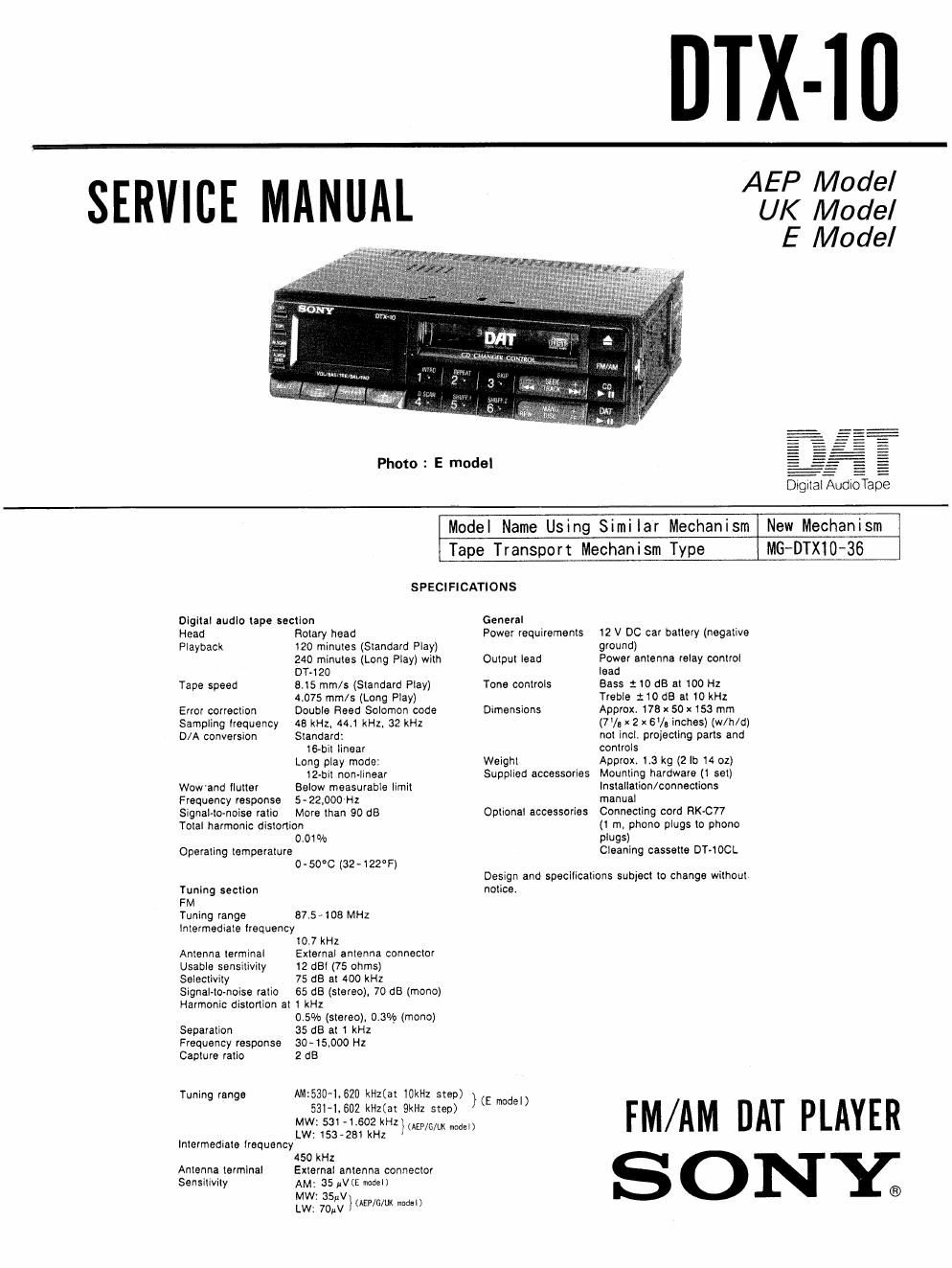
Sony dtx 10 service manual

This is the 54 pages manual for sony dtx 10 service manual.
Read or download the pdf for free. If you want to contribute, please mail your pdfs to info@audioservicemanuals.com.

Page: 1 / 54
left right
sony dtx 10 service manual

Extracted text from sony dtx 10 service manual (Ocr-read)


Page 1

DTX-lll

ERVICE MANUAL

Photo : E model

AEP Model
UK Model
E Model

Digital AudioTape

Model Name Using Similar Mechanism New Mechanism

Tape Transport Mechanism Type MG-DTXlO-36

SPECIFICATIONS

Digital audio tape section

Head Rotary head

Playback 120 minutes (Standard Play)
240 minutes (Long Play) with
DT~120

Tape speed 615 mm/s (Standard Play)

4075 mm/s (Long Play)
Double Reed Solomon code
48 kHz. 44.1 kHz. 32 kHz
Standard:

16-bit linear
Long play mode:

12bit non-linear
Below measurable limit

Error correction
Sampling ltequency
D/A conversion

Wowand tlutter
Frequency response 5»22.000 Hz
Signal-to-noise ratio More than 90 dB
Total harmonic distortion

0.01%
Operating temperature

0 - 50C (32-122°F)

Tuning section

FM

Tuning range
Intermediate lrequency
10] kHz

External antenna connector
12 dBl (75 ohms)

87.5-108 MHz

Antenna terminal
Usable sensitivity
Selectivity 75 dB at 400 kHz
Signal-to-noise ratio 65 dB (stereo), 70 dB (mono)
Harmonic distortion at 1 kHz

0.5% (stereo), 0.3% (mono)
Separation 35 dB at 1 kHz
Frequency response 30-15000 Hz
Capture ratio 2 dB

Tuning range

MW: 5: - L602 kHz

LW: 153-281 kHz
Intermediate trequency

450 kHz
External antenna connector
AM: 35 thE modal)

Mw: asuv
LW: 70W }(AEP/G/Ul< nodal)

Antenna terminal
Sensitivity

AM:530-l,620 kHz(at iOkHz step)
5314.602 kHztat 9ka step)

}(AEF/G/UK model)

General

Power requirements 12 V DC car battery (negative
ground)

Output lead Power antenna relay control
lead

Bass :to dB at 100 Hz
Treble :10 dB at 10 kHz

Tone controls

Dimensions Approx 173 x 50 x 153 mm
(7/. x 2 x 6% inches) (w/h/d)
not incl. projecting parts and
controls

Weight Approx, 1.3 kg (2 lo 14 oz)

Supplied accessories Mounting hardware (1 set)
Installation/connections
manual

Connecting cord RK-C77

(t m. phono plugs to phono
plugs)

Cleaning cassette DT-tOCL

Optional accessories

Design and specifications subject to change without
notice

)(E model)

FM/AM DAT PLAYER
SONE

Page 2

fl DTX-1 0

TABLE OF CONTENTS

Sect-ion Title M
SECTION 1. GENERAL -------- ' r ----- 3
SECTION 2. DISASSEMBLY ---------- ' 9
SECTION 3. INSTALLATION' --------- H
SECTION 4. ADJUSTMENTS

4'1. Mechanical Adjustments - ------- 18

4-2. Electrical Adjustments - - - - - - -21
SECTION 5. DIAGRAMS

5-1. Block Diagram --------- - - 25

5-2. IC Pin Functions ------ - - - -29

5-3. Waveforms. . . . . ........ . . 39

5-4. Printed Wiring Boards

-Disita|/Servo Section- ----- - - - ~40

5-5. Schematic Diagram

-Disital/Servo Section- - - 43

5-6. Printed Wiring Boards

-Audio Section- ......... . . . .43

5-7. Schematic Diagram

-Audio Section- - - - . ......... 53
SECTION 6. EXPLODED VIEWS

6-1. Front Panel,Cover Assembles- - - - - -5l

6-2. Chassis Assemble ----------- 58

6-3, MD Section) ....... . ..... 59

6-4. MD Section(2) ........ . . . . .50

6-5. MD Section(3) ..... . ....... 61

6-6. MD Section(4) .......... . '62

67. MD Section(5)- - . . . . . . . .53
SECTION 7 ELECTRICAL PARTS LIST -------- 64

Flexible Circuit Board Repairing

0Keep the temperature of the soldering iron around

270'C during repairing.

0 Do not touch the soldering iron on the same con-

ductor of the circuit board (Within 3 times).

0 Be careful not to apply force on the conductor when

soldering or unsoldering. _

Notes on chip component replacement

I Never reuse a disconnected chip component.

0 Notice that the minus side of a tantalum capacitor

may be damaged by heat.