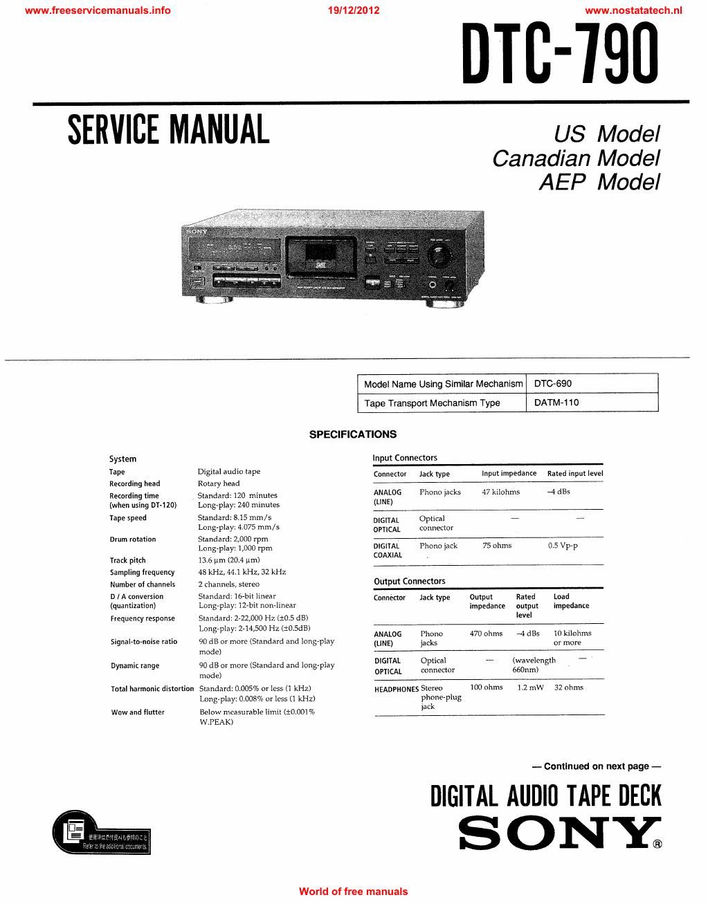
Sony dtc 790 tape service manual

This is the 53 pages manual for sony dtc 790 tape service manual.
Read or download the pdf for free. If you want to contribute, please mail your pdfs to info@audioservicemanuals.com.

Page: 1 / 53
left right
sony dtc 790 tape service manual

Extracted text from sony dtc 790 tape service manual (Ocr-read)


Page 1

www.freeservicemanuals.info

19/12/2012

www.nostatatech.n|

DIE-790

SERVICE MANUAL

US Model
Canadian Model
AEP Model

System
Tape
Recording head

Recording time
(when using DT-lzoi

Tape speed

Drum rotation

Track pitch
Sampling frequency
Number oi channels
D l A conversion

(quantization)
Frequency response
Signal-to-noise ratio
Dynamic range

Total harmonic distortion

Wow and flutter

Model Name Using Similar Mechanism DTC-690
Tape Transport Mechanism Type DATM-110
SPECIFICATIONS

Input Connectors
Dis 0" PB Connector Jack type Input impedance Rated input level
Rotary head
Standard: 120 minutes ANALOG Phone iacks 47 kilohms -4 am
Long-play: 240 minutes (UNE)
Standard: 8.15 mm/s DIGITAL opncal A #
Longplay: 4.075 mm /s MAL connector
Standard: 2,000 rpm
Long-play: 1,000 rpm DIGITAL Phone jack 75 ohms 0V5 Vp-p
13.6 um (20.4 pm) coAx'AL >
48 kHz, 44.] kHz, 32 kHz
2 channels, stereo Output connefios
Standard: 15) linear . Connector Jack type Output Rated Load
Long-play. 124 on'lmear impedance output impedance
Standard: -22,000 Hz (10.5 dB) IEVEI
L0ng-play:2-14,500 Hz (10.5w)

ANALOG Phone 470 ohms 4 st 10 kiloltms
90 dB or more (Standard and long-play (WE, jacks or more
mode)
90 dB or more (Standard and long-play D'G'm OPmal (wavelmgl -

OPTICAL connector 660nm)
mode)
Standard: 0.005% or less (1 kHz) HEADPHONES Stereo 100 ohms 1.2 mW 32 ohms
Long-play: 0.008% or less (1 kHz) phoneplug

jack

Below measurable limil (10.001 %
W.PEAK)

-- Continued on next page -

DIGITAL Allllll] TAPE DECK
S 0 NY;

World of free manuals

Page 2

www.freeservicemanuals.info

General section
Power requirements

Where purchased Power requirements

U5. Canadian model 120 V AC, 60 Hz

AEP. German model 220 - 240 V AC, 50/60 Hz

Power consumption 30 W

Approx 430 X122 x 32% mm (w/h/d)
(17 X 47/5 X 127/: inches)

Approx 5.0 kg (11 lb 0.4 oz)

Dimensions

Weight

Remote commander RM-DS (supplied)

Dimensions Approx 45 X 185 x 20 mm (w/ h/ d)
(13/Ie X 73/: x /Is inches)
Weight Approx 100 g (3.5 oz) incl. batteries

Supplied accessories

' Audio connecting Cords (2)

o Remote commander (remote) RM-D9 (I)

- Size-AA (R6) batteries (2)

' Operating instructions (I)

0 Warranly card (U.S.A. and Canadian models only)
(I)

Design and specifications are subject to change without notice.

Notes on chip component replacement

. Never reuse it disconnected chip component.

~ Notice that the minus side of a tantalum capacitor may be
damaged by heat.

SAFETY-RELATED COMPONENT WARNING !!

COMPONENTS IDENTIFIED BY MARK A OR DOTTED

LINE WITH MARK A ON THE SCHEMATIC DIAGRAMS
AND IN THE PARTS LIST ARE CRITICAL TO SAFE

OPERATION. REPLACE THESE COMPONENTS WITH
SONY PARTS WHOSE PART NUMBERS APPEAR AS
SHOWN IN THIS MANUAL OR IN SUPPLEMENTS
PUBLISHED BY SONY.

19/12/2012

TABLE OF CONTENTS
Sggtgn Tit g
SECTION 1. GENERAL .................................................. 4

Big-Q

SECTION 2. DISASSEMBLY
2-1. Case .................
2-2. Cassette Window
2-3. Mechanism Deck
24. Holder ...............
2~5. Cassette Compartment Motor (M901), Pulley,
Driving Gear and Slider .........................
2-6. Drum Driving Board and Driving Chassis
27. Drum ...........................
2-8. Capstan Motor (M902)

UlOIU'IO'I

\l\lchm

SECTION 3. ADJUSTMENTS
Notes When Making Adjustments ............................................. 8
3-1. Electrical Adjustments ...................................................... 9

SECTION 4. DIAGRAMS

4-1 . Circuit Boards Location .
4-2. Block Diagram ............
4-8. Schematic Diagram -- Main Section -
4-4. Printed Wiring Board - Main Section -- ........
4-5. Printed Wiring Board - Display, MD Section -
4»6. Schematic Diagram - Display, MD Section -.


4-7. IC Block Diagrams ............................................................ 33
4-8. IC Pin Functions
. IC304 CXDZSOSQ (DSP) ............................................... 35

' IC310 CXP87532-015Q (Main, Mech Control)
- ICBOI CXP82316054Q (Display Control)
0 IC802 MSM6338RS (Meter IO)


SECTION 5. EXPLODED VIEWS
5-1. Case Section .......
5-2. Front Panel Section
5-3. Chassis Section ......
5-4. Mechanism Deck Section-1 .
5-5. Mechanism Deck Section-2 .
5<6. Mechanism Deck Section-3 (DATM-110)
5-7. Mechanism Deck Section-4 (DATM-IIO)

SECTION 6. ELECTRICAL PARTS LIST...

ATTENTION Au COMPOSANT AYANT RAPPORT
A LA sEcuniTEii

LEs COMPOSANTS iDENTIPIE's PAR UNE MAROUE A
sun LES DIAGRAMMES SCHEMATIOUES ET LA LISTE
DEs PIECES SONT camouss Poun LA sEcuanE'
DE FONCTIONNEMENT. NE REMPLACER CES
COMPOSANTS ouE PAR DEs PIECES SONY DONT
LES NUMEnos SONT OONNEs DANS CE MANUEL ou
DANS LES SUPPLEMENTS PUBLIEs PAR SONY.

could cause possible component damage.

PRECAUTIONS FOR INSPECTIONS AND REPAIR WITH POWER OFF

Before beginning repair work after turning OFF the main switch, be sure to first remove CN901 (EH5P), 902 (EHGP) of
the main board. When assembling the equipment, be sure to plug this connector last.

Even with the main switch turned Off, there still remain electrical charges in part of the power circuit. Therefore,
plugging in or removing the connector could cause the power supply terminal to short with an adjacent terminal. This

World of free manuals

www.nostatatech.n|